How to Use 2437603-1: Examples, Pinouts, and Specs
Introduction
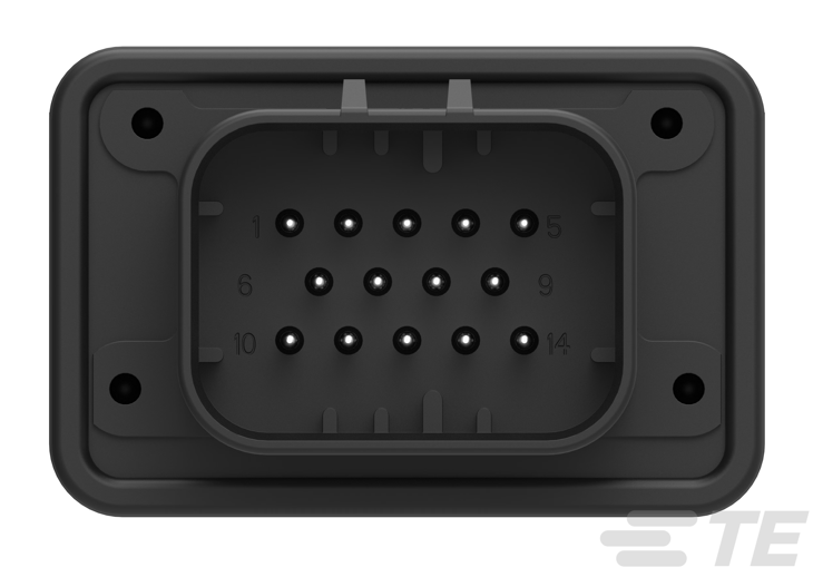
The HEADER ASSEMBLY, 14 POSITION, RIGHT ANGLE, AMPSEAL (Manufacturer Part ID: 2437603-1) is a robust and reliable connector manufactured by TE Connectivity. This component is designed to provide secure and durable electrical connections in a variety of applications. Its 14-position configuration and right-angle design make it ideal for compact and space-constrained setups. The AMPSEAL series is known for its high performance in harsh environments, making it suitable for automotive, industrial, and outdoor applications.
Explore Projects Built with 2437603-1


Explore Projects Built with 2437603-1
Common Applications and Use Cases
- Automotive systems, including engine control units (ECUs) and sensors
- Industrial machinery and equipment
- Outdoor electronic systems exposed to moisture or vibration
- Robotics and automation systems
- Power distribution and signal transmission in compact circuits
Technical Specifications
Key Technical Details
| Parameter | Value |
|---|---|
| Manufacturer | TE Connectivity |
| Part Number | 2437603-1 |
| Series | AMPSEAL |
| Number of Positions | 14 |
| Orientation | Right Angle |
| Mounting Type | Through-Hole |
| Contact Termination | Solder |
| Operating Temperature | -40°C to +125°C |
| Voltage Rating | Up to 250V |
| Current Rating | Up to 8A per contact |
| Housing Material | Thermoplastic, UL 94V-0 flame retardant |
| Sealing | IP67-rated for water and dust resistance |
Pin Configuration and Descriptions
The HEADER ASSEMBLY, 14 POSITION, RIGHT ANGLE, AMPSEAL features 14 pins arranged in a single row. Below is the pin configuration:
| Pin Number | Description | Notes |
|---|---|---|
| 1 | Power Input (+) | Main power supply input |
| 2 | Ground (-) | Common ground connection |
| 3-12 | Signal/Control Lines | For data or control signals |
| 13 | Reserved | For future use or customization |
| 14 | Shield/Ground | Optional shielding connection |
Note: Pin assignments may vary depending on the specific application. Always refer to the circuit design or datasheet for exact pin usage.
Usage Instructions
How to Use the Component in a Circuit
Mounting the Connector:
- The connector is designed for through-hole mounting. Ensure the PCB has appropriately sized holes to accommodate the pins.
- Align the connector with the PCB and solder each pin securely to ensure a reliable connection.
Wiring and Mating:
- Use compatible AMPSEAL female connectors or harnesses for mating.
- Ensure proper alignment during mating to avoid damage to the pins or housing.
Environmental Considerations:
- The IP67 rating ensures protection against dust and temporary immersion in water. However, ensure proper sealing during installation to maintain this protection.
Voltage and Current Ratings:
- Do not exceed the specified voltage (250V) or current (8A per contact) ratings to prevent overheating or damage.
Important Considerations and Best Practices
- Soldering: Use a temperature-controlled soldering iron to avoid overheating the thermoplastic housing.
- Cable Strain Relief: Use strain relief mechanisms to prevent stress on the solder joints or pins.
- Testing: After installation, test the connections for continuity and proper functionality.
- Compatibility: Ensure the mating connector is from the AMPSEAL series to guarantee a secure fit.
Example: Connecting to an Arduino UNO
While the HEADER ASSEMBLY is not directly designed for microcontroller use, it can be adapted for signal transmission. Below is an example of connecting the component to an Arduino UNO for reading sensor data:
// Example: Reading a signal from Pin 3 of the AMPSEAL connector
// Ensure proper wiring between the AMPSEAL connector and Arduino UNO

const int signalPin = 3; // Pin 3 on the AMPSEAL connector
const int arduinoPin = A0; // Connect to Arduino analog pin A0

void setup() {
  pinMode(arduinoPin, INPUT); // Set Arduino pin as input
  Serial.begin(9600); // Initialize serial communication
}

void loop() {
  int sensorValue = analogRead(arduinoPin); // Read signal from AMPSEAL
  Serial.print("Sensor Value: ");
  Serial.println(sensorValue); // Print the value to the Serial Monitor
  delay(500); // Wait for 500ms before the next reading
}
Note: Ensure proper voltage level shifting if the signal voltage exceeds the Arduino's input voltage range (0-5V).
Troubleshooting and FAQs
Common Issues Users Might Face
Loose Connections:
- Problem: The connector does not fit securely or connections are intermittent.
- Solution: Ensure proper alignment during mating and check for damaged pins or housing.
Overheating:
- Problem: The connector or PCB heats up during operation.
- Solution: Verify that the current does not exceed 8A per contact. Check for short circuits.
Signal Interference:
- Problem: Noise or interference in signal lines.
- Solution: Use shielded cables and connect the shield to Pin 14 (Shield/Ground).
Water Ingress:
- Problem: Moisture enters the connector, causing malfunction.
- Solution: Ensure the connector is properly sealed and the mating connector is compatible.
Solutions and Tips for Troubleshooting
- Inspect the Connector: Regularly check for physical damage, such as bent pins or cracks in the housing.
- Test Continuity: Use a multimeter to verify electrical continuity across the pins.
- Follow the Datasheet: Always refer to the official datasheet for detailed specifications and guidelines.
By following these instructions and best practices, the HEADER ASSEMBLY, 14 POSITION, RIGHT ANGLE, AMPSEAL can be effectively integrated into your electronic projects, ensuring reliable and long-lasting performance.