Cirkit Designer Logo
Cirkit Designer
Your all-in-one circuit design IDE
Home / 
Component Documentation

How to Use Level Gauge Indicator: Examples, Pinouts, and Specs

Image of Level Gauge Indicator
Cirkit Designer LogoDesign with Level Gauge Indicator in Cirkit Designer

Introduction

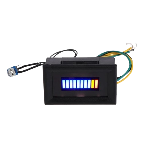
The Level Gauge Indicator is a device designed to measure and display the level of a liquid within a container. It is commonly used in industrial, automotive, and household applications to monitor liquid levels such as water, fuel, or chemicals. The device typically operates using floats, ultrasonic sensors, or capacitive sensing to provide accurate and reliable readings.

Explore Projects Built with Level Gauge Indicator

Use Cirkit Designer to design, explore, and prototype these projects online. Some projects support real-time simulation. Click "Open Project" to start designing instantly!
Interactive LED and Buzzer Circuit with Switch Controls
Image of 630 commission: A project utilizing Level Gauge Indicator in a practical application
This is a manually controlled indicator and alert system. It uses switches and pushbuttons to activate red and green LEDs, buzzers, and bulbs, indicating different states or alerts. The circuit is powered by a 6V battery and includes resistors to protect the LEDs from excessive current.
Cirkit Designer LogoOpen Project in Cirkit Designer
Arduino UNO Based Gas Detection System with MQ Sensors and DHT11
Image of IOT project: A project utilizing Level Gauge Indicator in a practical application
This circuit is designed to monitor gas levels using MQ135 and MQ-4 gas sensors and to measure temperature and humidity with a DHT11 sensor. It uses an Arduino UNO to read sensor data and control a green LED, a red LED, and a buzzer for visual and audible alerts. The green LED and buzzer are activated when high gas levels are detected, while the red LED indicates low gas levels.
Cirkit Designer LogoOpen Project in Cirkit Designer
Arduino-Controlled Ultrasonic Water Level Indicator with LCD Display and Relay Switching
Image of water: A project utilizing Level Gauge Indicator in a practical application
This circuit is designed to monitor water levels using an HC-SR04 Ultrasonic Sensor and display the information on an LCD I2C Display. An Arduino UNO controls the sensor to measure distance, calculates the water level as a percentage, and toggles a relay to control a pump based on the water level and manual input from a pushbutton. The system allows for manual override of the pump operation and stores the set water level threshold in EEPROM for persistent control across power cycles.
Cirkit Designer LogoOpen Project in Cirkit Designer
Arduino Nano Fuel Level and Temperature Monitoring System with OLED Display
Image of 1996_XP_MFD: A project utilizing Level Gauge Indicator in a practical application
This circuit is a fuel level and temperature monitoring system using an Arduino Nano, which reads sensor data from potentiometers and displays the information on an OLED screen. It controls LEDs to indicate critical levels: a red LED for low fuel, a yellow LED for high temperature, and additional LEDs for oil and battery status. The system also updates the display with the current readings and thresholds.
Cirkit Designer LogoOpen Project in Cirkit Designer

Explore Projects Built with Level Gauge Indicator

Use Cirkit Designer to design, explore, and prototype these projects online. Some projects support real-time simulation. Click "Open Project" to start designing instantly!
Image of 630 commission: A project utilizing Level Gauge Indicator in a practical application
Interactive LED and Buzzer Circuit with Switch Controls
This is a manually controlled indicator and alert system. It uses switches and pushbuttons to activate red and green LEDs, buzzers, and bulbs, indicating different states or alerts. The circuit is powered by a 6V battery and includes resistors to protect the LEDs from excessive current.
Cirkit Designer LogoOpen Project in Cirkit Designer
Image of IOT project: A project utilizing Level Gauge Indicator in a practical application
Arduino UNO Based Gas Detection System with MQ Sensors and DHT11
This circuit is designed to monitor gas levels using MQ135 and MQ-4 gas sensors and to measure temperature and humidity with a DHT11 sensor. It uses an Arduino UNO to read sensor data and control a green LED, a red LED, and a buzzer for visual and audible alerts. The green LED and buzzer are activated when high gas levels are detected, while the red LED indicates low gas levels.
Cirkit Designer LogoOpen Project in Cirkit Designer
Image of water: A project utilizing Level Gauge Indicator in a practical application
Arduino-Controlled Ultrasonic Water Level Indicator with LCD Display and Relay Switching
This circuit is designed to monitor water levels using an HC-SR04 Ultrasonic Sensor and display the information on an LCD I2C Display. An Arduino UNO controls the sensor to measure distance, calculates the water level as a percentage, and toggles a relay to control a pump based on the water level and manual input from a pushbutton. The system allows for manual override of the pump operation and stores the set water level threshold in EEPROM for persistent control across power cycles.
Cirkit Designer LogoOpen Project in Cirkit Designer
Image of 1996_XP_MFD: A project utilizing Level Gauge Indicator in a practical application
Arduino Nano Fuel Level and Temperature Monitoring System with OLED Display
This circuit is a fuel level and temperature monitoring system using an Arduino Nano, which reads sensor data from potentiometers and displays the information on an OLED screen. It controls LEDs to indicate critical levels: a red LED for low fuel, a yellow LED for high temperature, and additional LEDs for oil and battery status. The system also updates the display with the current readings and thresholds.
Cirkit Designer LogoOpen Project in Cirkit Designer

Common Applications and Use Cases

  • Monitoring water levels in tanks or reservoirs
  • Fuel level measurement in vehicles or storage tanks
  • Chemical level monitoring in industrial processes
  • Liquid level detection in household appliances (e.g., washing machines)
  • Agricultural irrigation systems

Technical Specifications

Below are the general technical specifications for a typical Level Gauge Indicator. Specific models may vary, so always refer to the manufacturer's datasheet for precise details.

Key Technical Details

  • Operating Voltage: 5V to 24V DC (depending on the model)
  • Current Consumption: 10mA to 50mA
  • Measurement Range: 0 to 100% of tank capacity
  • Accuracy: ±1% of full scale
  • Output Signal: Analog (0-5V), Digital (I2C, UART, or SPI), or Resistive
  • Operating Temperature: -10°C to 70°C
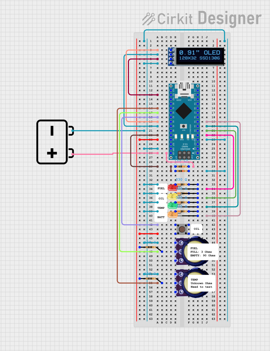
  • Sensor Type: Float-based, ultrasonic, or capacitive

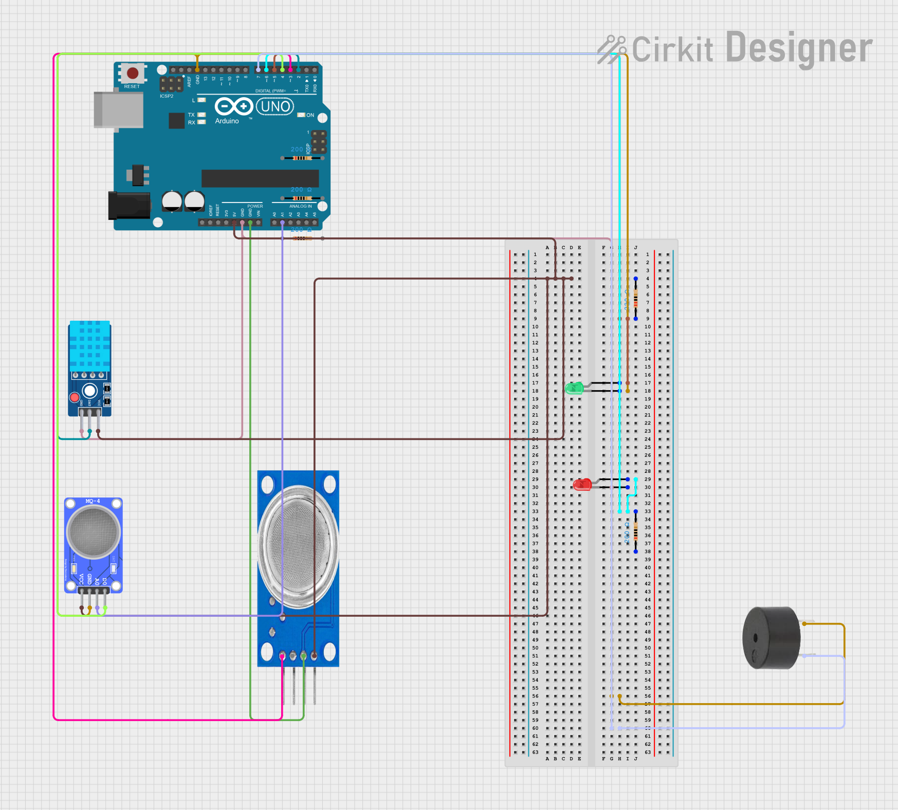
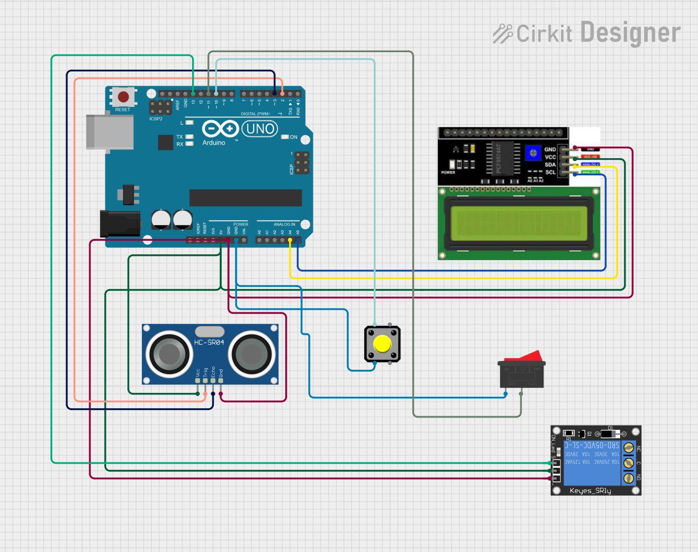
Pin Configuration and Descriptions

The pin configuration may vary depending on the type of Level Gauge Indicator. Below is an example for a digital ultrasonic-based indicator:

Pin Name Description
VCC Power supply input (5V or 12V DC)
GND Ground connection
TRIG Trigger pin for ultrasonic pulse
ECHO Echo pin for receiving ultrasonic signal
OUT Analog or digital output signal

For a float-based resistive indicator, the pin configuration might look like this:

Pin Name Description
VCC Power supply input (5V or 12V DC)
GND Ground connection
OUT Resistive output signal

Usage Instructions

How to Use the Component in a Circuit

  1. Power Supply: Connect the VCC pin to a regulated power source (e.g., 5V or 12V DC) and the GND pin to the ground of the circuit.
  2. Signal Connection:
    • For analog output models, connect the OUT pin to an analog input pin of your microcontroller or ADC (Analog-to-Digital Converter).
    • For digital output models, connect the TRIG and ECHO pins to digital I/O pins of your microcontroller.
  3. Calibration: Some models may require calibration to ensure accurate readings. Follow the manufacturer's instructions for calibration procedures.
  4. Integration with Microcontroller: Use the appropriate code or library to read and process the output signal.

Important Considerations and Best Practices

  • Ensure the sensor is installed at the correct height and orientation for accurate readings.
  • Avoid exposing the sensor to extreme temperatures or corrosive liquids unless it is specifically designed for such conditions.
  • Use proper filtering or signal conditioning to reduce noise in the output signal.
  • For ultrasonic models, ensure there are no obstructions between the sensor and the liquid surface.

Example Code for Arduino UNO (Ultrasonic Model)

// Example code to interface an ultrasonic Level Gauge Indicator with Arduino UNO
// This code measures the liquid level and displays it on the Serial Monitor.

#define TRIG_PIN 9  // Define the TRIG pin
#define ECHO_PIN 10 // Define the ECHO pin

void setup() {
  pinMode(TRIG_PIN, OUTPUT); // Set TRIG pin as output
  pinMode(ECHO_PIN, INPUT);  // Set ECHO pin as input
  Serial.begin(9600);        // Initialize serial communication
}

void loop() {
  long duration;
  float distance;

  // Send a 10us pulse to trigger the ultrasonic sensor
  digitalWrite(TRIG_PIN, LOW);
  delayMicroseconds(2);
  digitalWrite(TRIG_PIN, HIGH);
  delayMicroseconds(10);
  digitalWrite(TRIG_PIN, LOW);

  // Measure the time it takes for the echo to return
  duration = pulseIn(ECHO_PIN, HIGH);

  // Calculate the distance (in cm) based on the speed of sound
  distance = (duration * 0.034) / 2;

  // Display the distance on the Serial Monitor
  Serial.print("Liquid Level: ");
  Serial.print(distance);
  Serial.println(" cm");

  delay(1000); // Wait for 1 second before the next reading
}

Troubleshooting and FAQs

Common Issues Users Might Face

  1. No Output Signal:

    • Check the power supply connections and ensure the correct voltage is applied.
    • Verify that the sensor is properly connected to the microcontroller.
  2. Inaccurate Readings:

    • Ensure the sensor is installed correctly and is not tilted or obstructed.
    • Check for electrical noise or interference in the circuit.
  3. Intermittent Signal Loss:

    • Inspect the wiring for loose connections or damaged cables.
    • Ensure the sensor is not exposed to extreme environmental conditions.
  4. Ultrasonic Sensor Not Responding:

    • Verify that the TRIG and ECHO pins are correctly connected to the microcontroller.
    • Ensure the sensor is not blocked by any objects.

Solutions and Tips for Troubleshooting

  • Use a multimeter to check the voltage levels at the sensor pins.
  • Test the sensor in a controlled environment to rule out external factors.
  • For ultrasonic models, ensure the sensor is clean and free from dust or debris.
  • Consult the manufacturer's datasheet for specific troubleshooting steps.

By following this documentation, users can effectively integrate and troubleshoot a Level Gauge Indicator in their projects.