Cirkit Designer Logo
Cirkit Designer
Your all-in-one circuit design IDE
Home / 
Component Documentation

How to Use TCA9548 8-Way: Examples, Pinouts, and Specs

Image of TCA9548 8-Way
Cirkit Designer LogoDesign with TCA9548 8-Way in Cirkit Designer

Introduction

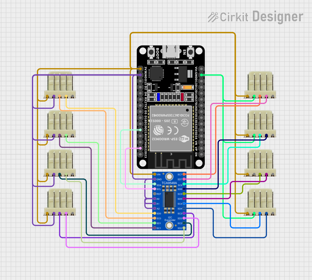
The TCA9548 is an 8-channel I2C multiplexer designed to simplify communication between a master device and multiple I2C devices. It allows the master to select one of eight downstream channels, enabling seamless management of multiple I2C devices on a single bus. This is particularly useful in applications where devices share the same I2C address, as the TCA9548 eliminates address conflicts by isolating each device on its own channel.

Explore Projects Built with TCA9548 8-Way

Use Cirkit Designer to design, explore, and prototype these projects online. Some projects support real-time simulation. Click "Open Project" to start designing instantly!
ESP32-Based I2C Multiplexer Interface
Image of 8 light sensors: A project utilizing TCA9548 8-Way in a practical application
This circuit utilizes an ESP32 microcontroller to interface with multiple I2C devices through an Adafruit TCA9548A I2C multiplexer. The ESP32 communicates with the TCA9548A via I2C, and the multiplexer allows for up to eight separate I2C buses, each connected to a 5-pin relimate connector. This setup enables the ESP32 to manage multiple I2C devices that may share the same address, by selecting which bus is active at any given time.
Cirkit Designer LogoOpen Project in Cirkit Designer
ESP32-Based I2C Communication Hub with Multiplexer and Expander
Image of Lights: A project utilizing TCA9548 8-Way in a practical application
This circuit features an Olimex ESP32-EVB microcontroller unit (MCU) for processing and connectivity, interfaced with an MCP23017 I/O expander and an Adafruit TCA9548A I2C multiplexer to expand the number of I/O lines and allow multiple I2C devices to communicate with the MCU over the same bus. Pull-up resistors are connected to the I2C lines for proper bus operation, and both the MCP23017 and TCA9548A have their reset lines pulled high, likely for normal operation without external reset control.
Cirkit Designer LogoOpen Project in Cirkit Designer
Cellular-Enabled IoT Device with Real-Time Clock and Power Management
Image of LRCM PHASE 2 BASIC: A project utilizing TCA9548 8-Way in a practical application
This circuit features a LilyGo-SIM7000G module for cellular communication and GPS functionality, interfaced with an RTC DS3231 for real-time clock capabilities. It includes voltage sensing through two voltage sensor modules, and uses an 8-channel opto-coupler for isolating different parts of the circuit. Power management is handled by a buck converter connected to a DC power source and batteries, with a fuse for protection and a rocker switch for on/off control. Additionally, there's an LED for indication purposes.
Cirkit Designer LogoOpen Project in Cirkit Designer
Configurable Battery-Powered RF Signal Transmitter with DIP Switch Settings
Image of fyp transmitter: A project utilizing TCA9548 8-Way in a practical application
This circuit appears to be a configurable encoder system with an RF transmission capability. The encoder's address pins (A0-A7) are connected to a DIP switch for setting the address, and its data output (DO) is connected to an RF transmitter, allowing the encoded signal to be wirelessly transmitted. The circuit is powered by a 9V battery, regulated to 5V by a 7805 voltage regulator, and includes a diode for polarity protection. Tactile switches are connected to the encoder's data inputs (D1-D3), and an LED with a current-limiting resistor indicates power or activity.
Cirkit Designer LogoOpen Project in Cirkit Designer

Explore Projects Built with TCA9548 8-Way

Use Cirkit Designer to design, explore, and prototype these projects online. Some projects support real-time simulation. Click "Open Project" to start designing instantly!
Image of 8 light sensors: A project utilizing TCA9548 8-Way in a practical application
ESP32-Based I2C Multiplexer Interface
This circuit utilizes an ESP32 microcontroller to interface with multiple I2C devices through an Adafruit TCA9548A I2C multiplexer. The ESP32 communicates with the TCA9548A via I2C, and the multiplexer allows for up to eight separate I2C buses, each connected to a 5-pin relimate connector. This setup enables the ESP32 to manage multiple I2C devices that may share the same address, by selecting which bus is active at any given time.
Cirkit Designer LogoOpen Project in Cirkit Designer
Image of Lights: A project utilizing TCA9548 8-Way in a practical application
ESP32-Based I2C Communication Hub with Multiplexer and Expander
This circuit features an Olimex ESP32-EVB microcontroller unit (MCU) for processing and connectivity, interfaced with an MCP23017 I/O expander and an Adafruit TCA9548A I2C multiplexer to expand the number of I/O lines and allow multiple I2C devices to communicate with the MCU over the same bus. Pull-up resistors are connected to the I2C lines for proper bus operation, and both the MCP23017 and TCA9548A have their reset lines pulled high, likely for normal operation without external reset control.
Cirkit Designer LogoOpen Project in Cirkit Designer
Image of LRCM PHASE 2 BASIC: A project utilizing TCA9548 8-Way in a practical application
Cellular-Enabled IoT Device with Real-Time Clock and Power Management
This circuit features a LilyGo-SIM7000G module for cellular communication and GPS functionality, interfaced with an RTC DS3231 for real-time clock capabilities. It includes voltage sensing through two voltage sensor modules, and uses an 8-channel opto-coupler for isolating different parts of the circuit. Power management is handled by a buck converter connected to a DC power source and batteries, with a fuse for protection and a rocker switch for on/off control. Additionally, there's an LED for indication purposes.
Cirkit Designer LogoOpen Project in Cirkit Designer
Image of fyp transmitter: A project utilizing TCA9548 8-Way in a practical application
Configurable Battery-Powered RF Signal Transmitter with DIP Switch Settings
This circuit appears to be a configurable encoder system with an RF transmission capability. The encoder's address pins (A0-A7) are connected to a DIP switch for setting the address, and its data output (DO) is connected to an RF transmitter, allowing the encoded signal to be wirelessly transmitted. The circuit is powered by a 9V battery, regulated to 5V by a 7805 voltage regulator, and includes a diode for polarity protection. Tactile switches are connected to the encoder's data inputs (D1-D3), and an LED with a current-limiting resistor indicates power or activity.
Cirkit Designer LogoOpen Project in Cirkit Designer

Common Applications and Use Cases

  • Managing multiple I2C devices with identical addresses
  • Expanding the number of I2C devices on a single bus
  • Sensor arrays in robotics and industrial automation
  • Multi-display systems
  • Data acquisition systems

Technical Specifications

The TCA9548 is a versatile and robust component. Below are its key technical details:

Parameter Value
Operating Voltage 1.65V to 5.5V
I2C Bus Speed Up to 400 kHz (Fast Mode)
Channels 8
I2C Address Range 0x70 to 0x77 (configurable)
Current Consumption 3 µA (typical, standby mode)
Operating Temperature -40°C to +85°C
Package Type TSSOP-16, QFN-16

Pin Configuration and Descriptions

The TCA9548 has 16 pins, as described in the table below:

Pin Number Pin Name Description
1 A0 Address selection bit 0
2 A1 Address selection bit 1
3 A2 Address selection bit 2
4 VCC Power supply input (1.65V to 5.5V)
5 SDA I2C data line (master side)
6 SCL I2C clock line (master side)
7 RESET Active-low reset input
8 GND Ground
9-16 SDx/SCx I2C data (SDx) and clock (SCx) lines for channels 0 to 7 (downstream devices)

Usage Instructions

The TCA9548 is straightforward to use in I2C-based systems. Below are the steps and considerations for integrating it into your circuit:

How to Use the TCA9548 in a Circuit

  1. Power the Device: Connect the VCC pin to a power supply (1.65V to 5.5V) and the GND pin to ground.
  2. Set the I2C Address: Configure the address by connecting the A0, A1, and A2 pins to either VCC (logic high) or GND (logic low). This determines the base address (0x70 to 0x77).
  3. Connect the I2C Bus: Attach the SDA and SCL lines from the master device to the TCA9548's SDA and SCL pins.
  4. Connect Downstream Devices: Attach the SDA and SCL lines of each downstream I2C device to the corresponding SDx and SCx pins of the TCA9548.
  5. Control the Multiplexer: Use the master device to send commands to the TCA9548, selecting the desired channel(s) for communication.

Important Considerations and Best Practices

  • Pull-Up Resistors: Ensure proper pull-up resistors are present on the SDA and SCL lines. Typically, 4.7kΩ resistors are used.
  • Channel Selection: Only one channel can be active at a time. Sending a control byte to the TCA9548 determines which channel is active.
  • Reset Functionality: Use the RESET pin to reset the device if communication issues occur.
  • Voltage Compatibility: Ensure that the voltage levels of the master and downstream devices are compatible with the TCA9548.

Example Code for Arduino UNO

Below is an example of how to use the TCA9548 with an Arduino UNO to communicate with a device on channel 0:

#include <Wire.h> // Include the Wire library for I2C communication

#define TCA9548_ADDRESS 0x70 // Base address of the TCA9548

void selectChannel(uint8_t channel) {
  // Ensure the channel is within the valid range (0-7)
  if (channel > 7) return;

  Wire.beginTransmission(TCA9548_ADDRESS); // Start communication with TCA9548
  Wire.write(1 << channel); // Send the control byte to select the channel
  Wire.endTransmission(); // End the transmission
}

void setup() {
  Wire.begin(); // Initialize I2C communication
  Serial.begin(9600); // Start serial communication for debugging

  Serial.println("Selecting channel 0...");
  selectChannel(0); // Select channel 0
}

void loop() {
  // Add your code to communicate with the device on channel 0
  delay(1000); // Delay for demonstration purposes
}

Troubleshooting and FAQs

Common Issues and Solutions

  1. No Communication with Downstream Devices

    • Cause: Incorrect channel selection or wiring issues.
    • Solution: Verify the channel selection command and check all connections.
  2. Address Conflicts

    • Cause: Multiple devices on the same channel with the same address.
    • Solution: Ensure only one device is connected to each channel.
  3. Device Not Responding

    • Cause: Incorrect I2C address configuration.
    • Solution: Double-check the A0, A1, and A2 pin connections to set the correct address.
  4. High Power Consumption

    • Cause: Pull-up resistors with low resistance values.
    • Solution: Use appropriate pull-up resistor values (e.g., 4.7kΩ).

FAQs

Q: Can I activate multiple channels simultaneously?
A: No, the TCA9548 allows only one channel to be active at a time.

Q: What happens if the RESET pin is left unconnected?
A: The RESET pin has an internal pull-up resistor, so it can be left unconnected. However, connecting it to a microcontroller for manual resets is recommended.

Q: Can the TCA9548 work with 3.3V and 5V devices simultaneously?
A: Yes, the TCA9548 supports level translation between 1.65V and 5.5V, but ensure proper pull-up resistors are used for each voltage level.

Q: How do I know which channel is currently active?
A: The TCA9548 does not provide feedback on the active channel. You must track the channel selection in your code.