How to Use md10-pot: Examples, Pinouts, and Specs
Introduction
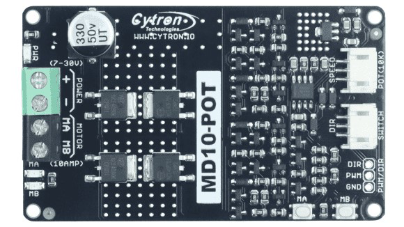
The MD10-Pot by Cytron is a versatile potentiometer designed for adjusting voltage levels in electronic circuits. It provides variable resistance, making it ideal for fine-tuning signal levels, controlling the brightness of LEDs, or adjusting the speed of motors. Its robust design and precision make it suitable for both hobbyist and professional applications.
Explore Projects Built with md10-pot


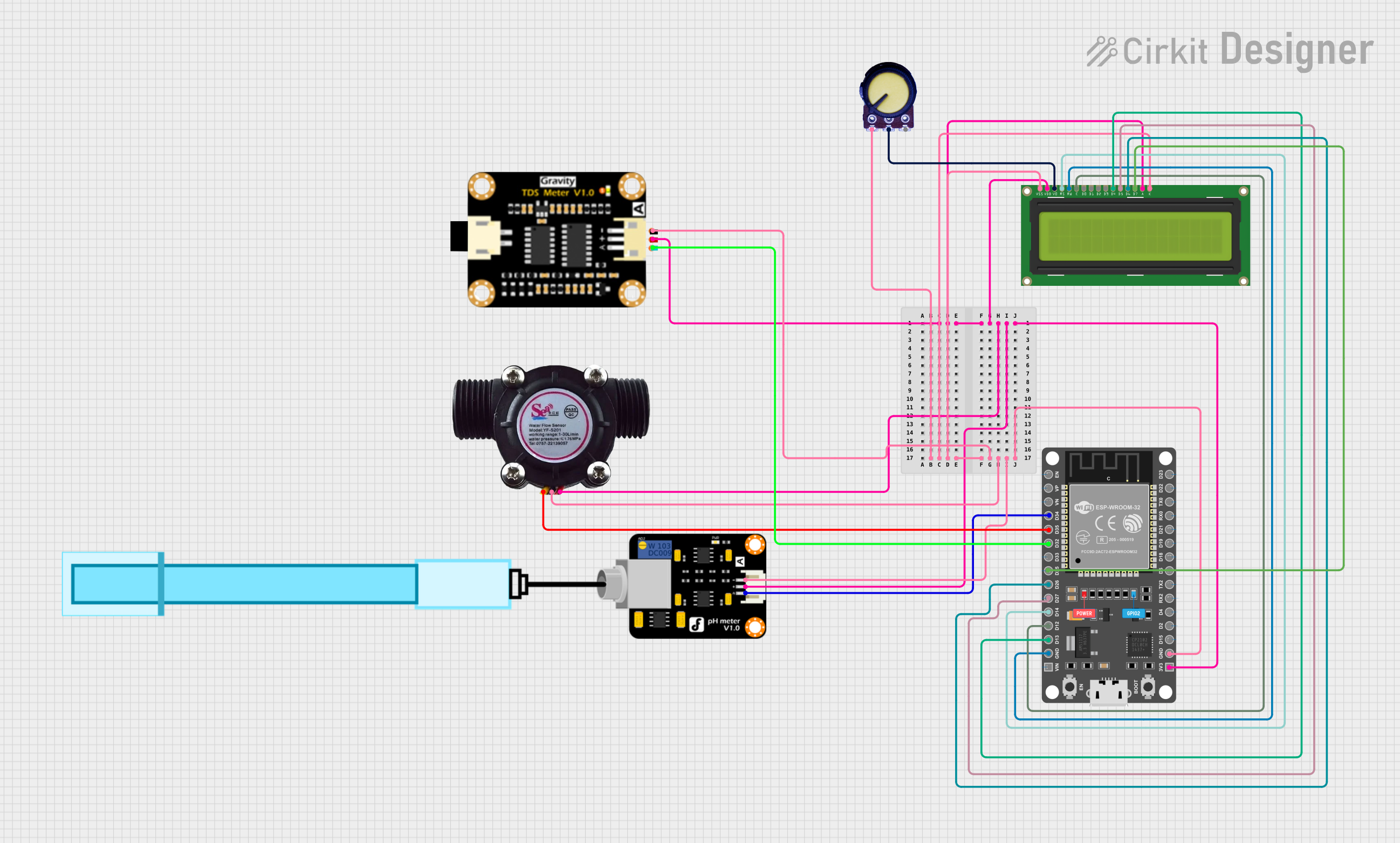
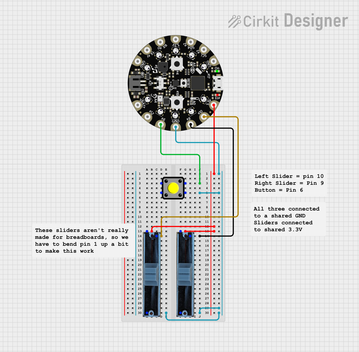
Explore Projects Built with md10-pot
Common Applications and Use Cases
- Adjusting signal levels in audio circuits
- Controlling the brightness of LEDs
- Speed control for DC motors
- Voltage divider circuits
- Calibration and tuning in measurement devices
Technical Specifications
The MD10-Pot is a high-quality potentiometer with the following key specifications:
| Parameter | Value |
|---|---|
| Resistance Range | 10 kΩ |
| Power Rating | 0.5 W |
| Tolerance | ±10% |
| Maximum Voltage | 50 V DC |
| Operating Temperature | -10°C to 70°C |
| Shaft Type | Knurled, 6 mm diameter |
| Adjustment Type | Rotary |
| Mounting Style | Through-hole |
Pin Configuration and Descriptions
The MD10-Pot has three pins, as described below:
| Pin | Name | Description |
|---|---|---|
| 1 | Terminal 1 | One end of the resistive track. Connect to the input voltage or ground. |
| 2 | Wiper | The adjustable middle pin. Outputs the variable voltage based on the rotation. |
| 3 | Terminal 2 | The other end of the resistive track. Connect to ground or input voltage. |
Usage Instructions
How to Use the MD10-Pot in a Circuit
Basic Voltage Divider Setup:
- Connect Terminal 1 to the input voltage (e.g., 5V).
- Connect Terminal 2 to ground.
- Connect the Wiper (Pin 2) to the circuit where you need the adjustable voltage.
Controlling LED Brightness:
- Place the MD10-Pot in series with an LED and a current-limiting resistor.
- Adjust the potentiometer to vary the brightness of the LED.
Interfacing with Arduino UNO:
- Connect Terminal 1 to the 5V pin on the Arduino.
- Connect Terminal 2 to the GND pin on the Arduino.
- Connect the Wiper (Pin 2) to an analog input pin (e.g., A0) on the Arduino.
Example Arduino Code
The following code reads the potentiometer value and adjusts the brightness of an LED connected to pin 9.
// Define pin connections
const int potPin = A0;  // Potentiometer wiper connected to analog pin A0
const int ledPin = 9;   // LED connected to digital pin 9 (PWM)

// Variable to store potentiometer value
int potValue = 0;

void setup() {
  pinMode(ledPin, OUTPUT);  // Set LED pin as output
  Serial.begin(9600);       // Initialize serial communication for debugging
}

void loop() {
  // Read the potentiometer value (0-1023)
  potValue = analogRead(potPin);

  // Map the potentiometer value to PWM range (0-255)
  int ledBrightness = map(potValue, 0, 1023, 0, 255);

  // Set the LED brightness
  analogWrite(ledPin, ledBrightness);

  // Print the potentiometer value for debugging
  Serial.print("Potentiometer Value: ");
  Serial.println(potValue);

  delay(10);  // Small delay for stability
}
Important Considerations and Best Practices
- Avoid exceeding the maximum voltage rating of 50V DC to prevent damage.
- Use a current-limiting resistor when controlling LEDs to avoid overcurrent.
- Ensure proper grounding to minimize noise in sensitive circuits.
- Handle the potentiometer gently to avoid damaging the shaft or resistive track.
Troubleshooting and FAQs
Common Issues and Solutions
No Output Voltage from the Wiper:
- Ensure the potentiometer is properly connected to the circuit.
- Verify that the input voltage is within the specified range.
Inconsistent or Noisy Output:
- Check for loose connections or poor soldering.
- Clean the potentiometer shaft if dirt or debris is causing poor contact.
Potentiometer Not Adjusting Properly:
- Verify that the potentiometer is not physically damaged.
- Ensure the wiper pin is correctly connected to the circuit.
FAQs
Q: Can the MD10-Pot handle AC voltage?
A: No, the MD10-Pot is designed for DC voltage applications only.
Q: What is the lifespan of the MD10-Pot?
A: The MD10-Pot is rated for approximately 10,000 cycles of operation under normal conditions.
Q: Can I use the MD10-Pot for high-power applications?
A: No, the MD10-Pot has a power rating of 0.5W and is not suitable for high-power applications. Use a higher-rated potentiometer or a different component for such cases.
Q: How do I mount the MD10-Pot on a PCB?
A: The MD10-Pot is designed for through-hole mounting. Insert the pins into the PCB holes and solder them securely.
By following this documentation, you can effectively integrate the MD10-Pot into your projects and troubleshoot any issues that arise.