How to Use MKS CANable V2: Examples, Pinouts, and Specs
Introduction
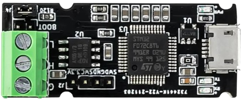
The MKS CANable V2 is a USB-to-CAN interface module designed by MakerBase. It enables seamless communication between a computer and devices on a CAN (Controller Area Network) bus. This compact and versatile device is widely used in applications such as robotics, automotive diagnostics, industrial automation, and IoT systems. Its compatibility with open-source tools and support for multiple CAN protocols make it a popular choice for developers and engineers working with CAN networks.
Explore Projects Built with MKS CANable V2


Explore Projects Built with MKS CANable V2
Common Applications and Use Cases
- Automotive diagnostics and ECU programming
- Robotics communication and control
- Industrial automation and monitoring
- IoT systems requiring CAN bus integration
- Debugging and testing CAN networks
Technical Specifications
The following table outlines the key technical details of the MKS CANable V2:
| Specification | Details |
|---|---|
| Microcontroller | STM32F042F6 |
| CAN Protocol Support | CAN 2.0A and CAN 2.0B |
| USB Interface | USB 2.0 (Micro-USB connector) |
| CAN Transceiver | MCP2551 or equivalent |
| Baud Rate | Up to 1 Mbps |
| Power Supply | 5V via USB |
| Operating Temperature | -40°C to 85°C |
| Dimensions | 40mm x 20mm x 10mm |
| Firmware | Compatible with Candlelight firmware and other open-source CAN firmware |
Pin Configuration and Descriptions
The MKS CANable V2 features a simple pinout for connecting to the CAN bus. The table below describes the pin configuration:
| Pin Name | Description |
|---|---|
| CAN_H | CAN High signal line |
| CAN_L | CAN Low signal line |
| GND | Ground connection |
| 5V | Optional 5V power output for CAN bus |
Usage Instructions
How to Use the MKS CANable V2 in a Circuit
Connect the CANable V2 to a Computer:
- Use a Micro-USB cable to connect the MKS CANable V2 to your computer. Ensure the necessary drivers are installed (e.g., STM32 Virtual COM Port drivers).
Connect to the CAN Bus:
- Connect the
CAN_HandCAN_Lpins of the CANable V2 to the corresponding lines on your CAN bus. - Optionally, connect the
GNDpin to the ground of the CAN bus for proper signal referencing.
- Connect the
Install and Configure Software:
- Use open-source tools like candleLight, SocketCAN (Linux), or CANutils to interface with the device.
- Configure the CAN baud rate and other parameters as required by your application.
Send and Receive CAN Messages:
- Use the software to send and receive CAN messages. For example, in Linux, you can use the
candumpandcansendcommands with SocketCAN.
- Use the software to send and receive CAN messages. For example, in Linux, you can use the
Important Considerations and Best Practices
- Termination Resistor: Ensure that the CAN bus is properly terminated with 120-ohm resistors at both ends of the bus. The MKS CANable V2 does not include an onboard termination resistor.
- Power Supply: The device is powered via USB. If your CAN bus requires additional power, use the
5Vpin to supply power (if supported by your setup). - Firmware Updates: The MKS CANable V2 supports firmware updates. Use tools like DFU-util to flash new firmware if needed.
- Isolation: The device does not provide galvanic isolation. For high-voltage or industrial applications, consider using an external isolator.
Example: Using MKS CANable V2 with Arduino UNO
The MKS CANable V2 can be used alongside an Arduino UNO to monitor or control a CAN bus. Below is an example of how to send a CAN message using the Arduino IDE and the CANable V2:
// Example: Sending a CAN message using MKS CANable V2 and Arduino UNO
// Ensure the CANable V2 is connected to the CAN bus and the computer

#include <SPI.h>
#include <mcp2515.h> // Include MCP2515 library for CAN communication

MCP2515 mcp2515(10); // Set CS pin to 10 for MCP2515

void setup() {
  Serial.begin(115200); // Initialize serial communication
  if (mcp2515.begin(MCP_ANY, CAN_500KBPS, MCP_8MHZ) == CAN_OK) {
    Serial.println("MCP2515 Initialized Successfully!");
  } else {
    Serial.println("Error Initializing MCP2515!");
    while (1);
  }
  mcp2515.setMode(MCP_NORMAL); // Set MCP2515 to normal mode
}

void loop() {
  struct can_frame canMsg;
  canMsg.can_id = 0x123; // Set CAN ID
  canMsg.can_dlc = 2;    // Set data length
  canMsg.data[0] = 0xAB; // First byte of data
  canMsg.data[1] = 0xCD; // Second byte of data

  if (mcp2515.sendMessage(&canMsg) == CAN_OK) {
    Serial.println("Message Sent Successfully!");
  } else {
    Serial.println("Error Sending Message!");
  }
  delay(1000); // Wait 1 second before sending the next message
}
Troubleshooting and FAQs
Common Issues and Solutions
Device Not Recognized by Computer:
- Ensure the correct drivers are installed (e.g., STM32 Virtual COM Port drivers).
- Try a different USB cable or port.
No Communication on CAN Bus:
- Verify the CAN bus is properly terminated with 120-ohm resistors.
- Check the baud rate configuration on both the CANable V2 and the CAN bus.
Firmware Issues:
- If the device is unresponsive, reflash the firmware using DFU mode and tools like DFU-util.
Data Corruption or Errors:
- Ensure proper grounding between the CANable V2 and the CAN bus.
- Check for electrical noise or interference on the CAN lines.
FAQs
Q: Can I use the MKS CANable V2 with Windows, Linux, and macOS?
A: Yes, the device is compatible with all major operating systems. Use appropriate tools like SocketCAN (Linux) or candleLight (Windows/macOS).Q: Does the MKS CANable V2 support CAN FD?
A: No, the MKS CANable V2 supports only CAN 2.0A and CAN 2.0B protocols.Q: How do I update the firmware?
A: Put the device into DFU mode by shorting the BOOT pins and use DFU-util to flash the firmware.Q: Is the device isolated?
A: No, the MKS CANable V2 does not provide galvanic isolation. Use an external isolator if required.