
How to Use RockerSwitch4Pin: Examples, Pinouts, and Specs
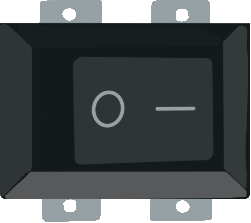
 Design with RockerSwitch4Pin in Cirkit Designer
Introduction
A 4-pin rocker switch is a type of electrical switch that toggles between two positions, typically ON and OFF, to control the flow of power in a circuit. It is designed with four pins, which allow for versatile wiring configurations, such as single-pole double-throw (SPDT) or double-pole single-throw (DPST) setups. This switch is widely used in household appliances, automotive systems, and electronic devices due to its durability and ease of use.
Explore Projects Built with RockerSwitch4Pin
 Open Project in Cirkit Designer
 Open Project in Cirkit Designer
 Open Project in Cirkit Designer
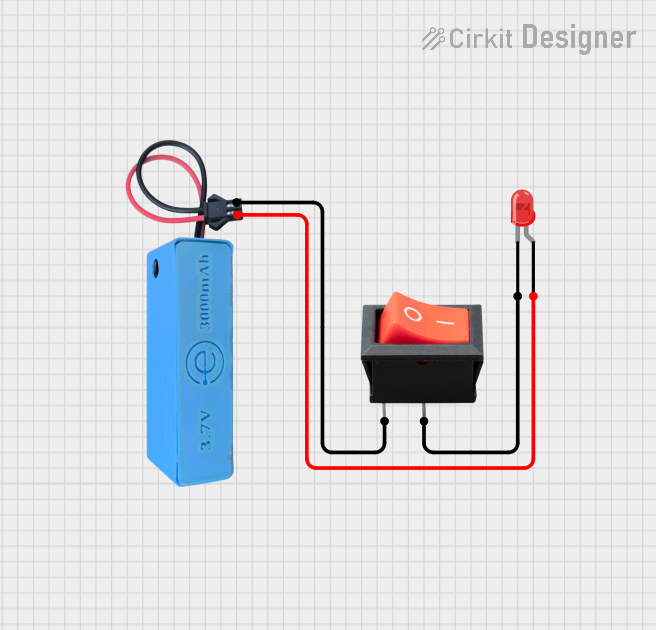 Open Project in Cirkit Designer
Explore Projects Built with RockerSwitch4Pin
Open Project in Cirkit DesignerOpen Project in Cirkit DesignerOpen Project in Cirkit DesignerOpen Project in Cirkit DesignerCommon Applications
- Power control in household appliances (e.g., lamps, fans)
- Automotive systems (e.g., dashboard controls)
- Electronic devices and DIY projects
- Industrial equipment for toggling power to machinery
Technical Specifications
Key Technical Details
- Switch Type: Rocker switch, 4-pin
- Positions: ON/OFF (or ON/ON depending on configuration)
- Voltage Rating: Typically 12V to 250V AC (varies by model)
- Current Rating: 6A to 16A (varies by model)
- Contact Resistance: ≤ 50 mΩ
- Insulation Resistance: ≥ 100 MΩ
- Operating Temperature: -25°C to 85°C
- Material: Plastic housing with metal contacts (often copper or brass)
Pin Configuration and Descriptions
The 4-pin rocker switch typically has the following pin layout:
| Pin Number | Label | Description |
|---|---|---|
| 1 | Input (L1) | Connects to the live (hot) wire of the power source. |
| 2 | Output (L2) | Connects to the load (e.g., device or appliance). |
| 3 | Input (L3) | Optional second live input for dual-pole configurations. |
| 4 | Output (L4) | Optional second output for dual-pole configurations or additional circuitry. |
Note: The exact pin labeling may vary depending on the manufacturer. Always refer to the datasheet for your specific model.
Usage Instructions
How to Use the Component in a Circuit
- Identify the Pins: Use the pin configuration table above or the datasheet to identify the input and output pins.
- Connect the Power Source: Attach the live wire of your power source to the input pin (L1). For dual-pole configurations, connect the second live wire to L3.
- Connect the Load: Attach the device or appliance you want to control to the output pin (L2). For dual-pole configurations, connect the second load to L4.
- Secure the Connections: Ensure all connections are tight and insulated to prevent short circuits.
- Test the Switch: Toggle the rocker switch to verify that it properly controls the power flow.
Important Considerations
- Voltage and Current Ratings: Ensure the switch's voltage and current ratings match your circuit requirements to avoid damage or overheating.
- Polarity: While rocker switches are generally non-polarized, ensure proper wiring to avoid functional issues.
- Mounting: Use the appropriate panel cutout size for secure installation. Most 4-pin rocker switches require a rectangular cutout.
- Debouncing: If using the switch in a digital circuit, consider implementing debouncing to avoid erratic behavior.
Example: Connecting to an Arduino UNO
A 4-pin rocker switch can be used as an input to an Arduino UNO to control an LED. Below is an example circuit and code:
Circuit Setup
- Connect one side of the rocker switch (L1) to the 5V pin on the Arduino.
- Connect the other side (L2) to a digital input pin (e.g., pin 2) on the Arduino.
- Add a pull-down resistor (10kΩ) between the digital input pin and ground to ensure a stable LOW state.
- Connect an LED to another digital pin (e.g., pin 13) with a current-limiting resistor (220Ω).
Arduino Code
// Define pin numbers
const int switchPin = 2;  // Pin connected to the rocker switch
const int ledPin = 13;    // Pin connected to the LED

void setup() {
  pinMode(switchPin, INPUT);  // Set the switch pin as input
  pinMode(ledPin, OUTPUT);    // Set the LED pin as output
  digitalWrite(ledPin, LOW);  // Ensure LED is off initially
}

void loop() {
  int switchState = digitalRead(switchPin);  // Read the state of the switch

  if (switchState == HIGH) {
    // If the switch is ON, turn the LED on
    digitalWrite(ledPin, HIGH);
  } else {
    // If the switch is OFF, turn the LED off
    digitalWrite(ledPin, LOW);
  }
}
Note: The pull-down resistor ensures the input pin reads LOW when the switch is open.
Troubleshooting and FAQs
Common Issues
Switch Not Working:
- Cause: Loose or incorrect wiring.
- Solution: Double-check all connections and ensure the correct pins are used.
Overheating:
- Cause: Exceeding the voltage or current rating of the switch.
- Solution: Verify that the switch's ratings match your circuit requirements.
Erratic Behavior in Digital Circuits:
- Cause: Switch bouncing.
- Solution: Implement hardware or software debouncing techniques.
LED Not Turning On in Arduino Circuit:
- Cause: Incorrect wiring or missing pull-down resistor.
- Solution: Ensure the switch is properly connected and the pull-down resistor is in place.
FAQs
Q: Can I use a 4-pin rocker switch for DC circuits?
- A: Yes, as long as the voltage and current ratings of the switch are suitable for your DC circuit.
Q: What is the difference between SPDT and DPST configurations?
- A: SPDT (Single-Pole Double-Throw) allows one input to toggle between two outputs. DPST (Double-Pole Single-Throw) allows two inputs to control two outputs simultaneously.
Q: How do I know which pin is which?
- A: Refer to the datasheet or use a multimeter to test continuity between pins in different switch positions.
By following this documentation, you can effectively use the RockerSwitch4Pin in your projects and troubleshoot common issues with ease.