
How to Use ESP32 WROOM 38 PINS: Examples, Pinouts, and Specs
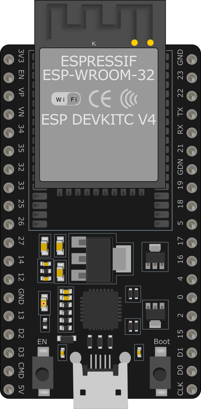
 Design with ESP32 WROOM 38 PINS in Cirkit Designer
Introduction
The ESP32 WROOM 38 PINS is a powerful microcontroller module designed for a wide range of applications, particularly in the Internet of Things (IoT) domain. It features integrated Wi-Fi and Bluetooth capabilities, making it ideal for wireless communication and smart device projects. With 38 GPIO pins, the ESP32 WROOM offers extensive interfacing options for sensors, actuators, and other peripherals, making it a versatile choice for hobbyists and professionals alike.
Explore Projects Built with ESP32 WROOM 38 PINS
 Open Project in Cirkit Designer
 Open Project in Cirkit Designer
 Open Project in Cirkit Designer
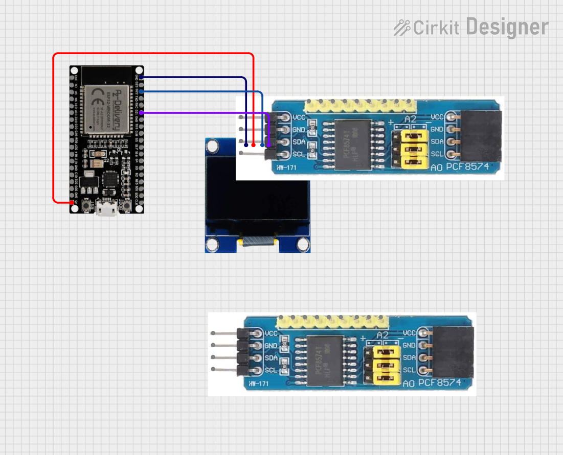 Open Project in Cirkit Designer
Explore Projects Built with ESP32 WROOM 38 PINS
Open Project in Cirkit DesignerOpen Project in Cirkit DesignerOpen Project in Cirkit DesignerOpen Project in Cirkit DesignerCommon Applications and Use Cases
- IoT devices and smart home automation
- Wireless sensor networks
- Wearable technology
- Robotics and automation systems
- Data logging and remote monitoring
- Prototyping and educational projects
Technical Specifications
The ESP32 WROOM 38 PINS module is built for high performance and flexibility. Below are its key technical details:
Key Technical Details
| Specification | Value |
|---|---|
| Microcontroller | Tensilica Xtensa LX6 dual-core processor |
| Clock Speed | Up to 240 MHz |
| Flash Memory | 4 MB (varies by model) |
| SRAM | 520 KB |
| Wi-Fi Standard | 802.11 b/g/n |
| Bluetooth | v4.2 BR/EDR and BLE |
| Operating Voltage | 3.3V |
| Input Voltage Range | 3.0V to 3.6V |
| GPIO Pins | 38 |
| ADC Channels | 18 (12-bit resolution) |
| DAC Channels | 2 |
| Communication Interfaces | UART, SPI, I2C, I2S, CAN, PWM |
| Power Consumption (Active) | ~160 mA |
| Power Consumption (Deep Sleep) | ~10 µA |
| Operating Temperature Range | -40°C to 85°C |
Pin Configuration and Descriptions
The ESP32 WROOM 38 PINS module has 38 GPIO pins, each with specific functions. Below is a summary of the pin configuration:
| Pin Number | Pin Name | Functionality |
|---|---|---|
| 1 | EN | Enable pin (active high) |
| 2 | IO0 | GPIO0, boot mode selection |
| 3 | IO1 (TX0) | GPIO1, UART0 TX |
| 4 | IO3 (RX0) | GPIO3, UART0 RX |
| 5 | IO4 | GPIO4, PWM, ADC, Touch |
| 6 | IO5 | GPIO5, PWM, ADC, Touch |
| ... | ... | ... (Refer to the datasheet for full details) |
| 37 | IO36 (VP) | GPIO36, ADC, VP (analog input) |
| 38 | IO39 (VN) | GPIO39, ADC, VN (analog input) |
Note: Some GPIO pins have specific restrictions or are reserved for internal use. Refer to the ESP32 datasheet for detailed pin functionality.
Usage Instructions
How to Use the ESP32 WROOM in a Circuit
Powering the Module:
- Provide a stable 3.3V power supply to the
3V3pin. Avoid exceeding the input voltage range (3.0V to 3.6V). - Connect the
GNDpin to the ground of your circuit.
- Provide a stable 3.3V power supply to the
Programming the ESP32:
- Use a USB-to-serial adapter or development board to upload code to the ESP32.
- Connect the
ENpin to 3.3V to enable the module. - For boot mode, connect
IO0to GND during programming.
Interfacing with Peripherals:
- Use the GPIO pins to connect sensors, actuators, or other devices.
- Configure the pins in your code for input, output, or alternate functions (e.g., ADC, PWM).
Wi-Fi and Bluetooth Setup:
- Use the ESP-IDF framework or Arduino IDE to configure Wi-Fi and Bluetooth.
- Ensure proper antenna placement for optimal wireless performance.
Important Considerations and Best Practices
- Voltage Levels: The ESP32 operates at 3.3V logic levels. Use level shifters if interfacing with 5V devices.
- Deep Sleep Mode: Utilize deep sleep mode to reduce power consumption in battery-powered applications.
- Pin Restrictions: Avoid using GPIO6 to GPIO11 as they are connected to the internal flash memory.
- Antenna Placement: Ensure the onboard antenna is not obstructed by metal or other materials to maintain signal strength.
Example Code for Arduino UNO
Below is an example of how to connect the ESP32 WROOM to a Wi-Fi network using the Arduino IDE:
#include <WiFi.h> // Include the WiFi library for ESP32

const char* ssid = "Your_SSID";       // Replace with your Wi-Fi SSID
const char* password = "Your_Password"; // Replace with your Wi-Fi password

void setup() {
  Serial.begin(115200); // Initialize serial communication at 115200 baud
  delay(1000);          // Wait for a moment to stabilize

  Serial.println("Connecting to Wi-Fi...");
  WiFi.begin(ssid, password); // Start Wi-Fi connection

  while (WiFi.status() != WL_CONNECTED) {
    delay(500); // Wait for connection
    Serial.print(".");
  }

  Serial.println("\nWi-Fi connected!");
  Serial.print("IP Address: ");
  Serial.println(WiFi.localIP()); // Print the assigned IP address
}

void loop() {
  // Add your main code here
}
Note: Replace
Your_SSIDandYour_Passwordwith your Wi-Fi credentials.
Troubleshooting and FAQs
Common Issues and Solutions
ESP32 Not Connecting to Wi-Fi:
- Ensure the SSID and password are correct.
- Check if the router is within range and supports 2.4 GHz Wi-Fi (ESP32 does not support 5 GHz).
Module Not Responding:
- Verify the power supply voltage is stable and within the 3.0V to 3.6V range.
- Check the connections, especially the
ENandIO0pins during programming.
GPIO Pin Not Working:
- Ensure the pin is not reserved for internal use (e.g., GPIO6 to GPIO11).
- Verify the pin mode is correctly configured in the code.
High Power Consumption:
- Use deep sleep mode to reduce power usage in idle states.
- Disable unused peripherals in your code.
FAQs
Q: Can I use the ESP32 WROOM with a 5V power supply?
A: No, the ESP32 operates at 3.3V. Use a voltage regulator or level shifter if interfacing with 5V systems.
Q: How do I reset the ESP32?
A: Pull the EN pin low momentarily to reset the module.
Q: Can I use the ESP32 for Bluetooth audio streaming?
A: Yes, the ESP32 supports Bluetooth audio streaming using the A2DP profile.
Q: What is the maximum range of the Wi-Fi connection?
A: The range depends on environmental factors but typically extends up to 100 meters in open spaces.
For more detailed information, refer to the official ESP32 datasheet and technical reference manual.