How to Use Mosfet module: Examples, Pinouts, and Specs
Introduction
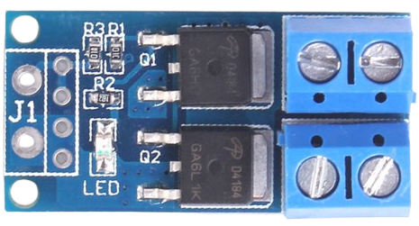
A MOSFET (Metal-Oxide-Semiconductor Field-Effect Transistor) module is a semiconductor device designed for switching or amplifying electronic signals. It is widely used in power electronics due to its ability to handle high voltages and currents efficiently, with minimal power loss. The module typically integrates one or more MOSFETs along with additional circuitry for ease of use in various applications.
Explore Projects Built with Mosfet module
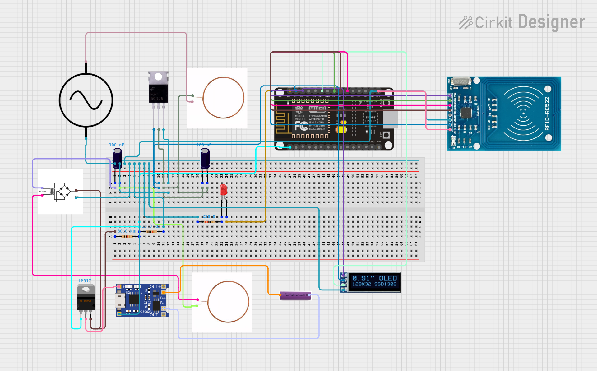
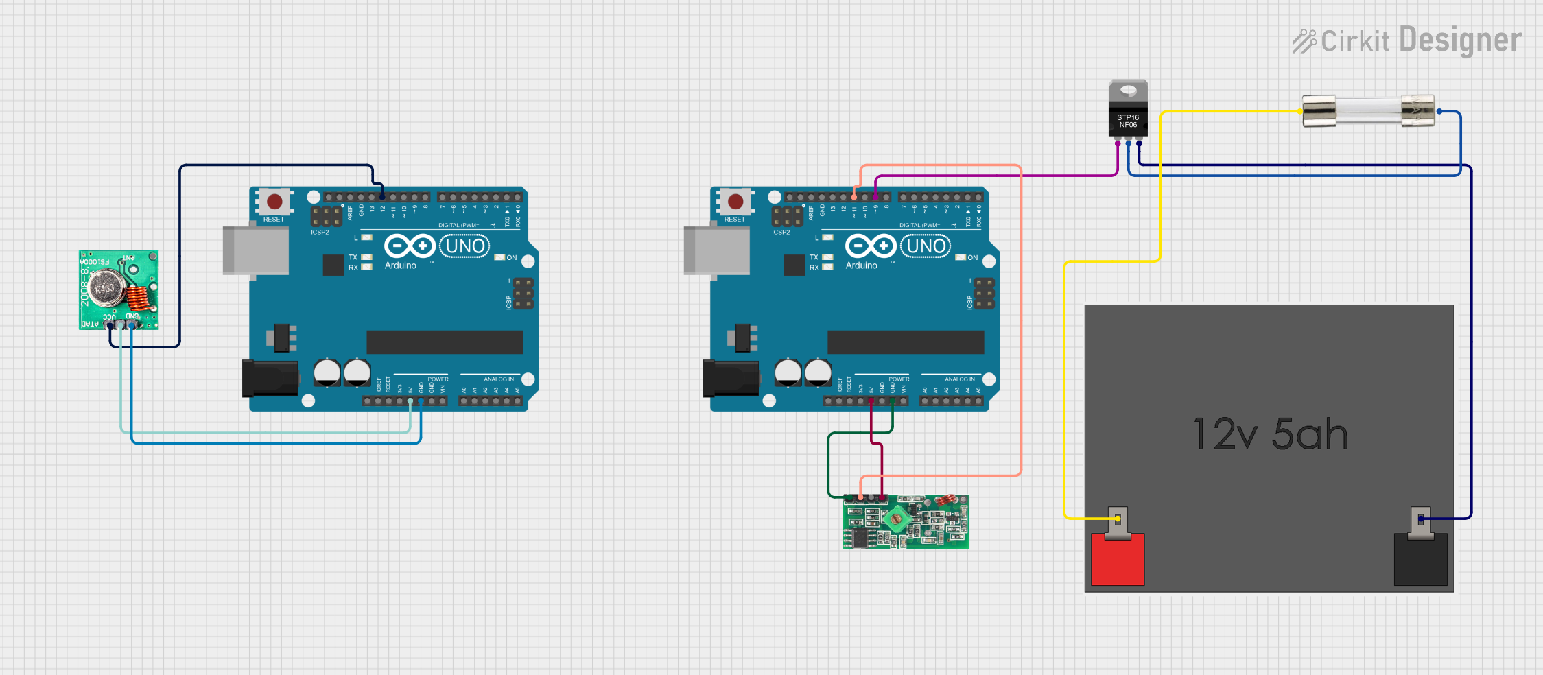

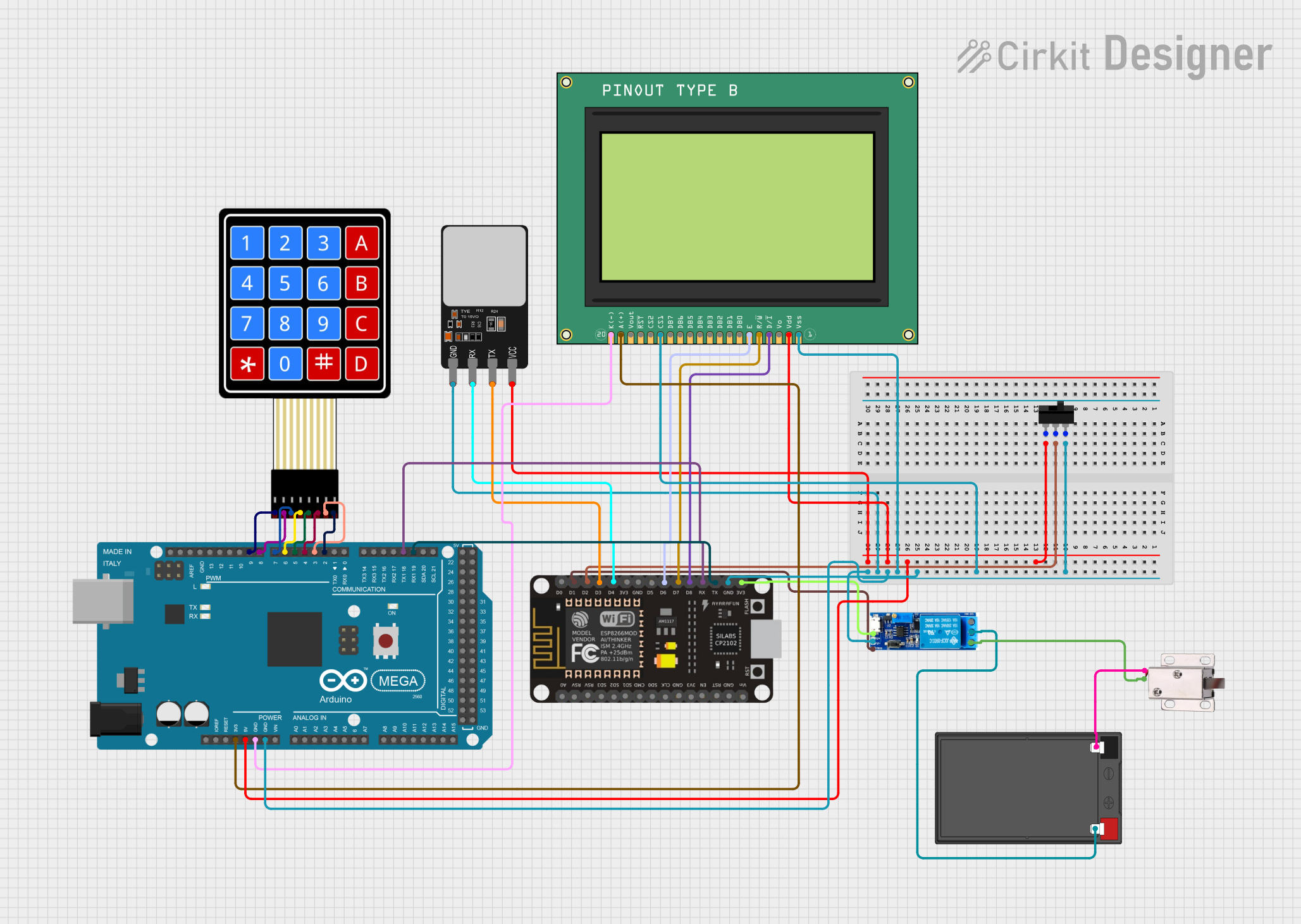
Explore Projects Built with Mosfet module
Common Applications and Use Cases
- Motor control in robotics and industrial automation
- DC-DC converters and power supplies
- LED dimming and lighting control
- High-speed switching in inverters
- Battery management systems in electric vehicles
Technical Specifications
Below are the general technical specifications for a typical MOSFET module. Always refer to the datasheet of the specific module for exact details.
Key Technical Details
- Operating Voltage Range: 5V to 60V (varies by module)
- Maximum Current: Up to 30A (depending on the MOSFET used)
- Gate Drive Voltage: 3.3V or 5V logic level compatible
- Switching Frequency: Up to 100 kHz
- On-Resistance (RDS(on)): As low as 0.01Ω
- Thermal Dissipation: Integrated heat sink for high-power applications
Pin Configuration and Descriptions
The MOSFET module typically has a 3-pin or 4-pin interface. Below is a table describing the pinout:
| Pin Name | Description |
|---|---|
| VIN | Input voltage (positive terminal) for the load |
| GND | Ground connection (negative terminal) |
| Signal | Control signal input (PWM or logic level) |
| VOUT | Output voltage to the load (optional) |
Some modules may include additional pins for features like enable/disable or feedback.
Usage Instructions
How to Use the MOSFET Module in a Circuit
- Power Supply: Connect the power supply's positive terminal to the
V<sub>IN</sub>pin and the negative terminal to theGNDpin. - Load Connection: Attach the load (e.g., motor, LED) between the
V<sub>OUT</sub>pin and the ground. - Control Signal: Provide a PWM or logic-level signal to the
Signalpin to control the MOSFET's switching. - Heat Management: Ensure proper heat dissipation by using the integrated heat sink or adding external cooling if necessary.
Important Considerations and Best Practices
- Gate Drive Voltage: Ensure the control signal voltage matches the module's requirements (e.g., 3.3V or 5V).
- Current Rating: Do not exceed the module's maximum current rating to avoid damage.
- Switching Frequency: Operate within the recommended frequency range to maintain efficiency.
- Protection: Use a flyback diode across inductive loads (e.g., motors) to prevent voltage spikes.
Example: Using the MOSFET Module with an Arduino UNO
Below is an example of controlling an LED using a MOSFET module and an Arduino UNO:
// Define the pin connected to the MOSFET module's Signal pin
const int mosfetPin = 9; // PWM pin on Arduino UNO

void setup() {
  pinMode(mosfetPin, OUTPUT); // Set the MOSFET pin as an output
}

void loop() {
  // Gradually increase brightness
  for (int brightness = 0; brightness <= 255; brightness++) {
    analogWrite(mosfetPin, brightness); // Send PWM signal to MOSFET
    delay(10); // Small delay for smooth transition
  }

  // Gradually decrease brightness
  for (int brightness = 255; brightness >= 0; brightness--) {
    analogWrite(mosfetPin, brightness); // Send PWM signal to MOSFET
    delay(10); // Small delay for smooth transition
  }
}
Troubleshooting and FAQs
Common Issues and Solutions
MOSFET Module Not Switching Properly
- Cause: Insufficient gate drive voltage.
- Solution: Verify that the control signal voltage matches the module's requirements (e.g., 3.3V or 5V).
Overheating
- Cause: Exceeding the current rating or poor heat dissipation.
- Solution: Use a heat sink or active cooling, and ensure the load current is within the module's limits.
Load Not Responding
- Cause: Incorrect wiring or damaged MOSFET.
- Solution: Double-check connections and test the module with a multimeter.
Voltage Spikes
- Cause: Inductive load without a flyback diode.
- Solution: Add a flyback diode across the load to suppress voltage spikes.
FAQs
Q: Can I use the MOSFET module with a 12V motor?
- A: Yes, as long as the module's voltage and current ratings are not exceeded.
Q: What is the maximum PWM frequency supported?
- A: Most modules support up to 100 kHz, but check the datasheet for your specific module.
Q: Do I need a resistor between the Arduino and the Signal pin?
- A: It is generally not required, but a small resistor (e.g., 220Ω) can be added for additional protection.
Q: Can I control multiple loads with one MOSFET module?
- A: No, each load should have its own MOSFET module to ensure proper operation and avoid overloading.
This documentation provides a comprehensive guide to understanding and using a MOSFET module effectively. Always consult the manufacturer's datasheet for specific details about your module.