How to Use disjoncteur 2P 63A: Examples, Pinouts, and Specs
Introduction
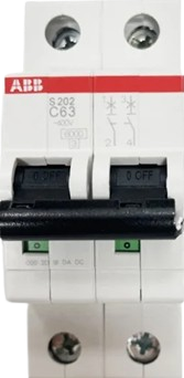
The Disjoncteur 2P 63A is a 2-pole circuit breaker rated for 63 amps. It is designed to protect electrical circuits from overloads and short circuits by automatically interrupting the current flow when abnormal conditions are detected. This component is widely used in residential, commercial, and industrial electrical systems to ensure safety and prevent damage to equipment.
Explore Projects Built with disjoncteur 2P 63A


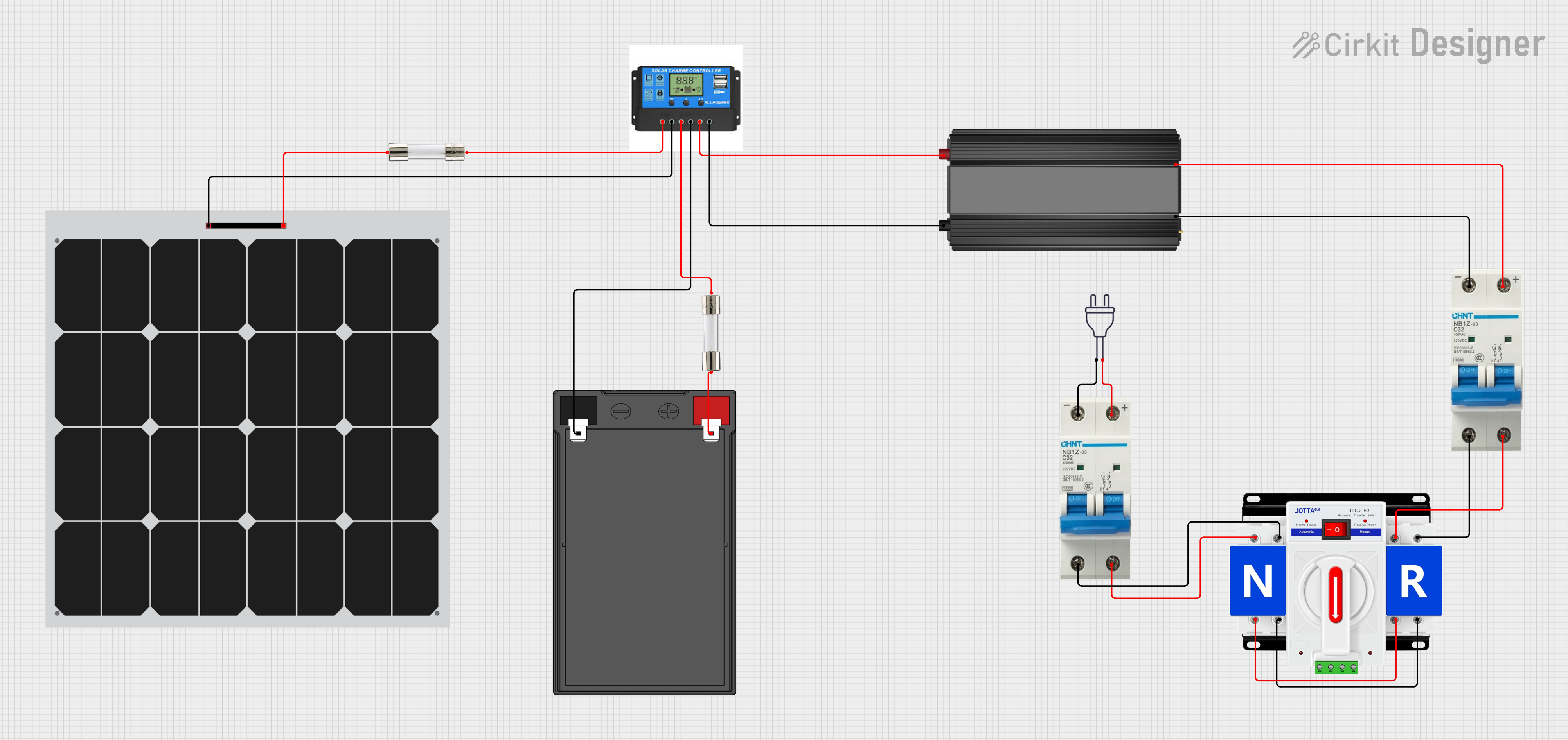
Explore Projects Built with disjoncteur 2P 63A
Common Applications and Use Cases
- Protection of electrical circuits in homes, offices, and industrial facilities.
- Safeguarding appliances and equipment from overcurrent and short circuits.
- Use in distribution boards for isolating and protecting specific circuits.
- Ensuring compliance with electrical safety standards.
Technical Specifications
Key Technical Details
| Parameter | Value |
|---|---|
| Rated Current (In) | 63 A |
| Number of Poles | 2 |
| Rated Voltage (Un) | 230/400 V AC |
| Breaking Capacity (Icu) | 6 kA |
| Frequency | 50/60 Hz |
| Trip Curve | Type C (standard for general loads) |
| Operating Temperature | -5°C to +40°C |
| Mounting Type | DIN rail |
| Standards Compliance | IEC/EN 60898-1 |
Pin Configuration and Descriptions
The Disjoncteur 2P 63A does not have traditional pins like electronic components but instead features terminals for connecting wires. Below is a description of the terminals:
| Terminal Name | Description |
|---|---|
| L1 | Input terminal for the first live wire. |
| L2 | Input terminal for the second live wire. |
| T1 | Output terminal for the first live wire. |
| T2 | Output terminal for the second live wire. |
Usage Instructions
How to Use the Component in a Circuit
Mounting the Circuit Breaker:
- Install the circuit breaker on a standard DIN rail in the distribution board.
- Ensure the breaker is securely locked into place.
Wiring the Circuit Breaker:
- Connect the incoming live wires to the input terminals (L1 and L2).
- Connect the outgoing live wires to the output terminals (T1 and T2).
- Tighten the terminal screws to ensure a secure connection.
Testing the Circuit Breaker:
- After installation, switch the breaker to the "ON" position.
- Use a test button (if available) to verify the tripping mechanism.
Operation:
- The breaker will automatically trip in case of an overload or short circuit.
- To reset, switch the breaker to the "OFF" position and then back to "ON" after resolving the issue.
Important Considerations and Best Practices
- Ensure the circuit breaker is rated appropriately for the circuit's current and voltage.
- Do not exceed the rated current of 63 A to avoid damage or failure.
- Regularly inspect the breaker for signs of wear or damage.
- Use proper tools and follow safety protocols during installation.
- Disconnect power before performing any maintenance or wiring.
Troubleshooting and FAQs
Common Issues and Solutions
| Issue | Possible Cause | Solution |
|---|---|---|
| Breaker trips frequently | Overload or short circuit in the circuit | Identify and fix the fault in the circuit. |
| Breaker does not trip during a fault | Faulty breaker or incorrect wiring | Replace the breaker or check wiring. |
| Difficulty in resetting the breaker | Internal mechanism is damaged | Replace the breaker. |
| Loose connections | Improper tightening of terminal screws | Re-tighten the screws securely. |
FAQs
Can this breaker be used for DC circuits?
No, the Disjoncteur 2P 63A is designed for AC circuits only.What does the "Type C" trip curve mean?
The Type C trip curve indicates that the breaker trips at 5 to 10 times the rated current, making it suitable for general-purpose loads with moderate inrush currents.How often should the breaker be tested?
It is recommended to test the breaker at least once a year to ensure proper functionality.Can I install this breaker without professional help?
While it is possible, it is highly recommended to have a licensed electrician perform the installation to ensure safety and compliance with local regulations.