How to Use Rotary Encoder: Examples, Pinouts, and Specs

Introduction
A rotary encoder is an electromechanical device that converts the angular position or motion of a shaft or axle into an analog or digital signal. It is widely used in applications requiring precise position sensing, speed measurement, or control. Rotary encoders are commonly found in robotics, CNC machines, industrial automation, and user interface devices like volume knobs or menu navigation controls.
Explore Projects Built with Rotary Encoder
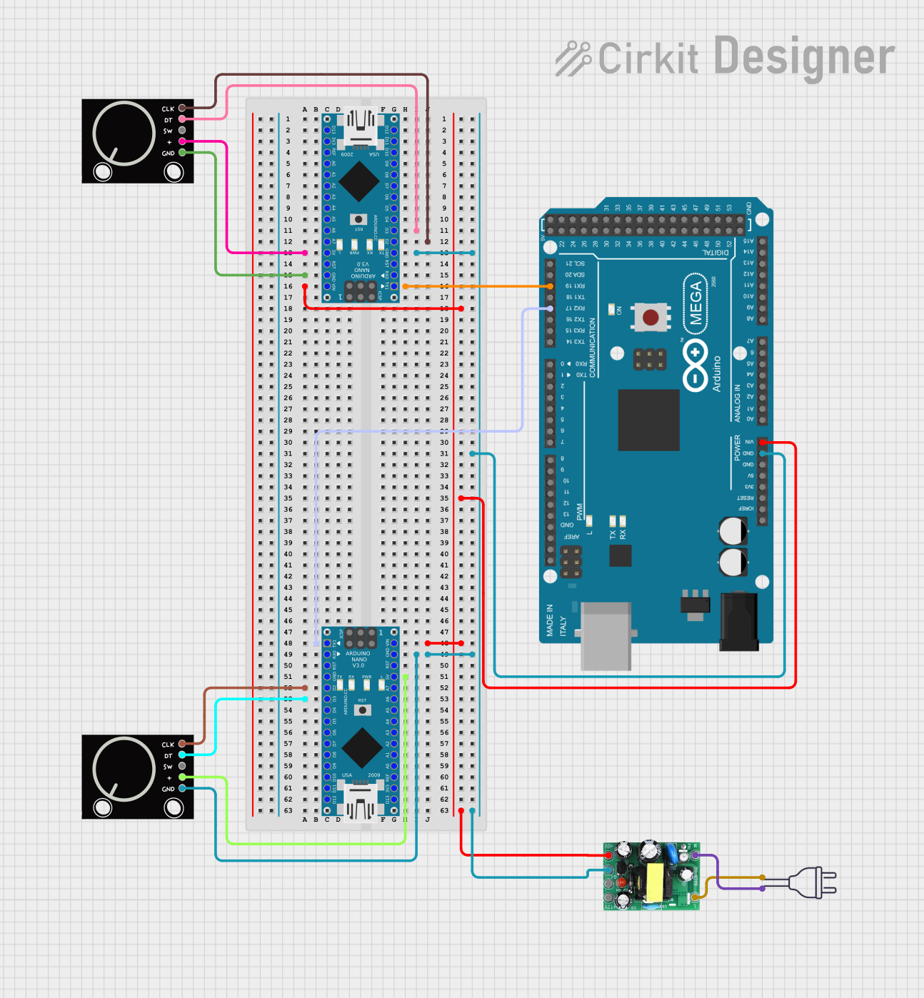
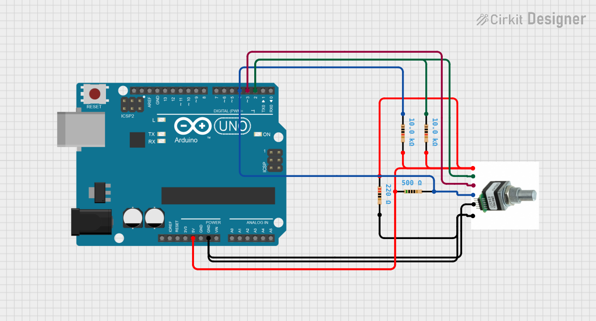
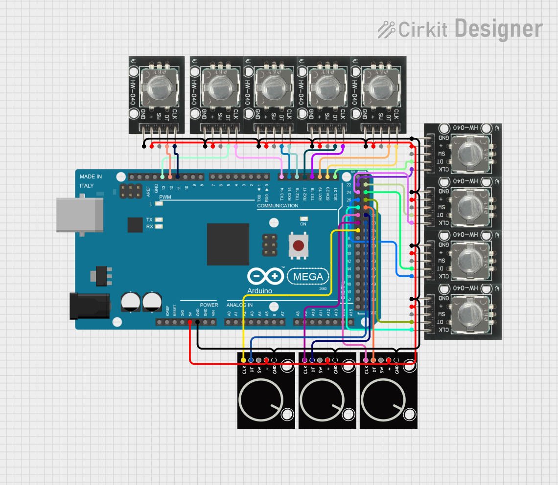
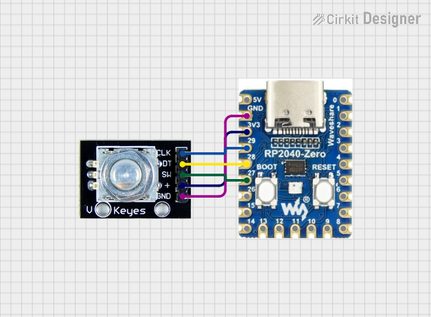
Explore Projects Built with Rotary Encoder
Common Applications:
- Position sensing in robotics and automation
- Speed measurement in motors and machinery
- User input devices (e.g., volume control, menu navigation)
- CNC machines and 3D printers for precise motion control
- Servo motor feedback systems
Technical Specifications
Key Technical Details:
- Operating Voltage: Typically 3.3V to 5V
- Output Type: Digital (Quadrature signals: A and B channels)
- Resolution: Depends on the encoder model (e.g., 20 pulses per revolution)
- Switch Functionality: Some rotary encoders include a push-button switch
- Debouncing: May require external debouncing for stable signals
- Operating Temperature: -20°C to +70°C (varies by model)
Pin Configuration and Descriptions:
| Pin Name | Description |
|---|---|
| GND | Ground connection for the encoder. |
| VCC | Power supply input (typically 3.3V or 5V). |
| CLK (A) | Channel A output signal for quadrature encoding. |
| DT (B) | Channel B output signal for quadrature encoding. |
| SW | Push-button switch output (active low, optional depending on the encoder model). |
Usage Instructions
How to Use the Rotary Encoder in a Circuit:
- Connect the Power Supply:
- Connect the VCC pin to a 3.3V or 5V power source.
- Connect the GND pin to the ground of your circuit.
- Connect the Output Pins:
- Connect the CLK (A) and DT (B) pins to digital input pins on your microcontroller.
- If the encoder has a push-button switch, connect the SW pin to another digital input pin.
- Read the Signals:
- Monitor the CLK and DT signals to determine the direction and number of steps.
- Use the SW pin to detect button presses if applicable.
- Debounce the Signals:
- Use hardware (e.g., capacitors) or software techniques to debounce the signals for stable readings.
Important Considerations and Best Practices:
- Debouncing: Rotary encoders often produce noisy signals. Use a debouncing circuit or software algorithm to filter out noise.
- Pull-up Resistors: If the encoder outputs are open-drain, use pull-up resistors on the CLK, DT, and SW pins.
- Signal Timing: Ensure your microcontroller can handle the signal frequency generated by the encoder.
- Mechanical Limitations: Avoid applying excessive force to the encoder shaft to prevent damage.
Example Code for Arduino UNO:
Below is an example of how to use a rotary encoder with an Arduino UNO:
// Rotary Encoder Example Code for Arduino UNO
// Connect CLK to pin 2, DT to pin 3, and SW to pin 4 (if applicable)

#define CLK 2  // Pin connected to the CLK (A) output of the encoder
#define DT 3   // Pin connected to the DT (B) output of the encoder
#define SW 4   // Pin connected to the SW (button) output of the encoder

int lastStateCLK;  // To store the previous state of the CLK pin
int currentStateCLK;  // To store the current state of the CLK pin
int counter = 0;  // Counter to track encoder position
bool buttonPressed = false;  // Flag for button press detection

void setup() {
  pinMode(CLK, INPUT);
  pinMode(DT, INPUT);
  pinMode(SW, INPUT_PULLUP);  // Enable internal pull-up resistor for SW pin
  Serial.begin(9600);

  // Read the initial state of the CLK pin
  lastStateCLK = digitalRead(CLK);
}

void loop() {
  // Read the current state of the CLK pin
  currentStateCLK = digitalRead(CLK);

  // If the state of CLK has changed, check the direction
  if (currentStateCLK != lastStateCLK) {
    // Read the state of the DT pin
    int stateDT = digitalRead(DT);

    // Determine the direction of rotation
    if (stateDT != currentStateCLK) {
      counter++;  // Clockwise rotation
    } else {
      counter--;  // Counterclockwise rotation
    }

    // Print the counter value to the Serial Monitor
    Serial.print("Position: ");
    Serial.println(counter);
  }

  // Update the last state of the CLK pin
  lastStateCLK = currentStateCLK;

  // Check if the button is pressed
  if (digitalRead(SW) == LOW) {
    if (!buttonPressed) {
      Serial.println("Button Pressed!");
      buttonPressed = true;
    }
  } else {
    buttonPressed = false;
  }
}
Troubleshooting and FAQs
Common Issues and Solutions:
No Output or Erratic Behavior:
- Cause: Poor connections or insufficient power supply.
- Solution: Check all connections and ensure the encoder is powered correctly.
Noisy or Unstable Signals:
- Cause: Signal bouncing or noise.
- Solution: Add hardware debouncing (e.g., capacitors) or implement software debouncing.
Incorrect Direction Detection:
- Cause: CLK and DT pins are swapped.
- Solution: Verify the wiring and ensure the CLK and DT pins are connected correctly.
Button Not Responding:
- Cause: Missing pull-up resistor or incorrect pin configuration.
- Solution: Enable the internal pull-up resistor or add an external one.
FAQs:
Q: Can I use a rotary encoder with a 3.3V microcontroller?
A: Yes, most rotary encoders work with 3.3V or 5V. Check the datasheet for compatibility.Q: How do I increase the resolution of my rotary encoder?
A: The resolution is determined by the encoder's design. To increase resolution, use an encoder with a higher pulse count per revolution.Q: Do I need external components to use a rotary encoder?
A: While not strictly necessary, external pull-up resistors and capacitors for debouncing can improve performance.Q: Can I use multiple rotary encoders in one project?
A: Yes, but ensure your microcontroller has enough digital input pins and processing power to handle multiple encoders.
This documentation provides a comprehensive guide to understanding and using a rotary encoder effectively in your projects.