Cirkit Designer Logo
Cirkit Designer
Your all-in-one circuit design IDE
Home / 
Component Documentation

How to Use dot matrix led: Examples, Pinouts, and Specs

Image of dot matrix led
Cirkit Designer LogoDesign with dot matrix led in Cirkit Designer

Introduction

A dot matrix LED display is an electronic visual display technology that uses a grid of light-emitting diodes (LEDs) as pixels for a full matrix of lights. Each LED can be independently turned on or off, allowing for the display of alphanumeric characters, symbols, and simple graphics or animations. Dot matrix LED displays are commonly used in public information displays, clocks, watches, calculators, and various other devices requiring a simple and effective method of displaying information.

Explore Projects Built with dot matrix led

Use Cirkit Designer to design, explore, and prototype these projects online. Some projects support real-time simulation. Click "Open Project" to start designing instantly!
Arduino UNO Controlled LED Matrix Display with Interactive Pushbuttons
Image of Cykel: A project utilizing dot matrix led in a practical application
This circuit features an Arduino UNO microcontroller connected to multiple 8x8 LED matrix displays and pushbuttons. The pushbuttons are interfaced with digital pins D2, D3, and D4 on the Arduino for input, while the LED matrices are connected to digital pins D5 through D10 for control signals. Additionally, there is a single red LED with a series resistor connected to pin D12, likely used as an indicator light.
Cirkit Designer LogoOpen Project in Cirkit Designer
ESP32-Controlled Dual 8x8 LED Matrix Display with NTP Time Synchronization
Image of time: A project utilizing dot matrix led in a practical application
This circuit features an ESP32 microcontroller connected to two cascaded 8x8 LED matrix displays, powered by a 3.3V battery. The ESP32 drives the displays to show time and other information, with the code indicating functionality for connecting to WiFi, synchronizing time via NTP, and displaying data on the matrices using custom fonts. Additionally, there is a separate 3.3V battery powering a red LED, which appears to function as a simple indicator light.
Cirkit Designer LogoOpen Project in Cirkit Designer
Arduino UNO Controlled LED Matrix and LCD Interface with Joystick Interaction
Image of Digital Game Circuit: A project utilizing dot matrix led in a practical application
This circuit features an Arduino UNO microcontroller interfaced with an 8x8 LED matrix, an LCD screen, and a KY-023 Dual Axis Joystick Module. The Arduino controls the LED matrix via digital pins D10-D12 and powers the matrix, LCD, and joystick module from its 5V output. The joystick's analog outputs are connected to the Arduino's analog inputs A0 and A1 for position sensing, while the LCD is controlled through digital pins D2-D6 and D13 for display purposes.
Cirkit Designer LogoOpen Project in Cirkit Designer
ESP8266 NodeMCU Controlled 8x8 LED Matrix Display
Image of Nodemcu: A project utilizing dot matrix led in a practical application
This circuit connects an ESP8266 NodeMCU microcontroller to an 8x8 LED matrix display. The NodeMCU controls the matrix using digital pins D5, D7, and D8 for chip select (CS), data input (DIN), and clock (CLK) signals, respectively. The circuit is designed to display patterns or characters on the LED matrix, which are driven by the microcontroller.
Cirkit Designer LogoOpen Project in Cirkit Designer

Explore Projects Built with dot matrix led

Use Cirkit Designer to design, explore, and prototype these projects online. Some projects support real-time simulation. Click "Open Project" to start designing instantly!
Image of Cykel: A project utilizing dot matrix led in a practical application
Arduino UNO Controlled LED Matrix Display with Interactive Pushbuttons
This circuit features an Arduino UNO microcontroller connected to multiple 8x8 LED matrix displays and pushbuttons. The pushbuttons are interfaced with digital pins D2, D3, and D4 on the Arduino for input, while the LED matrices are connected to digital pins D5 through D10 for control signals. Additionally, there is a single red LED with a series resistor connected to pin D12, likely used as an indicator light.
Cirkit Designer LogoOpen Project in Cirkit Designer
Image of time: A project utilizing dot matrix led in a practical application
ESP32-Controlled Dual 8x8 LED Matrix Display with NTP Time Synchronization
This circuit features an ESP32 microcontroller connected to two cascaded 8x8 LED matrix displays, powered by a 3.3V battery. The ESP32 drives the displays to show time and other information, with the code indicating functionality for connecting to WiFi, synchronizing time via NTP, and displaying data on the matrices using custom fonts. Additionally, there is a separate 3.3V battery powering a red LED, which appears to function as a simple indicator light.
Cirkit Designer LogoOpen Project in Cirkit Designer
Image of Digital Game Circuit: A project utilizing dot matrix led in a practical application
Arduino UNO Controlled LED Matrix and LCD Interface with Joystick Interaction
This circuit features an Arduino UNO microcontroller interfaced with an 8x8 LED matrix, an LCD screen, and a KY-023 Dual Axis Joystick Module. The Arduino controls the LED matrix via digital pins D10-D12 and powers the matrix, LCD, and joystick module from its 5V output. The joystick's analog outputs are connected to the Arduino's analog inputs A0 and A1 for position sensing, while the LCD is controlled through digital pins D2-D6 and D13 for display purposes.
Cirkit Designer LogoOpen Project in Cirkit Designer
Image of Nodemcu: A project utilizing dot matrix led in a practical application
ESP8266 NodeMCU Controlled 8x8 LED Matrix Display
This circuit connects an ESP8266 NodeMCU microcontroller to an 8x8 LED matrix display. The NodeMCU controls the matrix using digital pins D5, D7, and D8 for chip select (CS), data input (DIN), and clock (CLK) signals, respectively. The circuit is designed to display patterns or characters on the LED matrix, which are driven by the microcontroller.
Cirkit Designer LogoOpen Project in Cirkit Designer

Common Applications and Use Cases

  • Digital clocks and timers
  • Electronic billboards and signboards
  • Scoreboards in sports arenas
  • Information displays in public transport
  • User interfaces for various electronic devices

Technical Specifications

Key Technical Details

  • Operating Voltage: Typically 3.3V to 5V
  • Current Consumption: Depends on the number of LEDs lit and brightness level
  • Power Ratings: Varies with size and number of LEDs
  • Display Colors: Monochrome (commonly red, green, or blue)

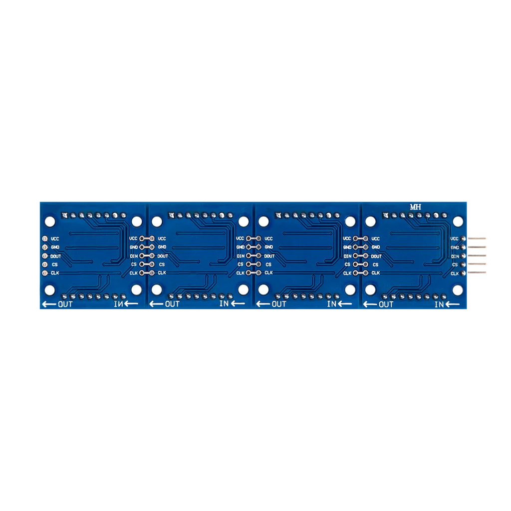
Pin Configuration and Descriptions

Pin Number Name Description
1 Vcc Power supply (3.3V to 5V)
2 GND Ground connection
3-10 Row Pins Controls the rows of the LED matrix
11-18 Column Pins Controls the columns of the LED matrix

Usage Instructions

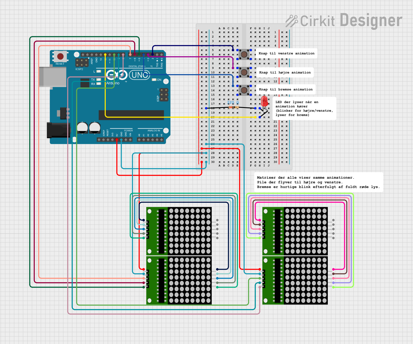
How to Use the Component in a Circuit

  1. Power Connections: Connect the Vcc pin to the positive supply and the GND pin to the ground.
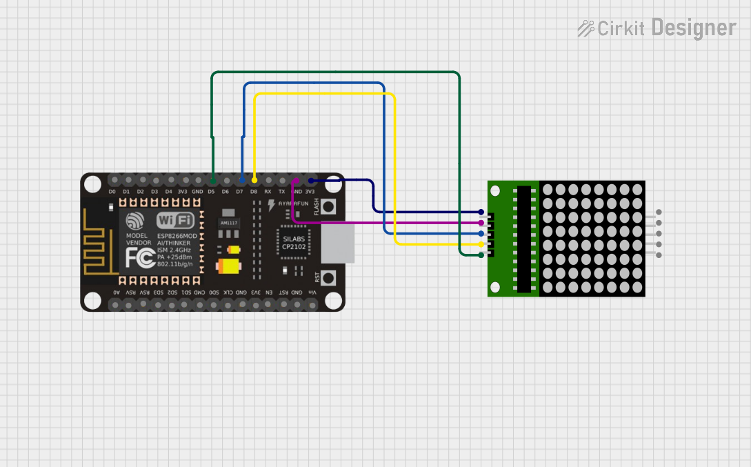
  2. Microcontroller Interface: Connect the row and column pins to the digital I/O pins of a microcontroller, such as an Arduino UNO.
  3. Current Limiting Resistors: Place a current limiting resistor in series with each row or column to prevent damage to the LEDs.
  4. Multiplexing: To control individual LEDs, use multiplexing by rapidly switching rows and columns on and off.

Important Considerations and Best Practices

  • Current Limiting: Always use appropriate current-limiting resistors to prevent LED burnout.
  • Refresh Rate: Ensure a high enough refresh rate to avoid visible flickering.
  • Brightness Control: Use pulse-width modulation (PWM) to control the brightness of the LEDs.
  • Heat Dissipation: Provide adequate heat sinking if the display is to be used at high brightness levels for extended periods.

Example Code for Arduino UNO

#include <LedControl.h>

// Pin configuration for the MAX7219 chip
int dataIn = 2;    // Connect to the DIN pin of the matrix
int clk = 3;       // Connect to the CLK pin of the matrix
int load = 4;      // Connect to the CS pin of the matrix
int maxInUse = 1;  // Number of MAX7219 chips in use

LedControl lc = LedControl(dataIn, clk, load, maxInUse);

void setup() {
  lc.shutdown(0, false);       // Wake up the display
  lc.setIntensity(0, 8);       // Set brightness level (0 is min, 15 is max)
  lc.clearDisplay(0);          // Clear display register
}

void loop() {
  // Display a single character 'A'
  byte charA[8] = {
    B00000000,
    B00111100,
    B01100110,
    B01100110,
    B01111110,
    B01100110,
    B01100110,
    B00000000
  };
  
  for (int i = 0; i < 8; i++) {
    lc.setRow(0, i, charA[i]);
  }
  
  delay(1000); // Keep 'A' displayed for 1000ms
}

Code Comments

  • The LedControl library is used for easy communication with the MAX7219 chip, which is a common driver for dot matrix LED displays.
  • The dataIn, clk, and load variables correspond to the DIN, CLK, and CS pins of the MAX7219 and should be connected to the respective pins on the Arduino.
  • The maxInUse variable indicates the number of daisy-chained MAX7219 chips.
  • The lc.shutdown() function wakes up the MAX7219 chip.
  • The lc.setIntensity() function sets the brightness of the display.
  • The lc.clearDisplay() function clears any residual data on the display.
  • The charA array represents the bitmap of the character 'A' to be displayed.
  • The lc.setRow() function sends the bitmap data to the display.

Troubleshooting and FAQs

Common Issues Users Might Face

  • Display Not Lighting Up: Check power supply connections and ensure that the current-limiting resistors are correctly placed.
  • Flickering Display: Increase the refresh rate or check for loose connections.
  • Dim Display: Adjust the brightness using the setIntensity() function or check if the power supply is adequate.

Solutions and Tips for Troubleshooting

  • Ensure Proper Connections: Double-check all wiring against the circuit diagram.
  • Use Serial Debugging: Print debug messages to the serial monitor to check if the microcontroller is sending the correct data.
  • Check Resistor Values: Verify that the current-limiting resistors are of the correct value to prevent either too much current or too little brightness.

FAQs

Q: Can I use any GPIO pins on the Arduino to connect to the dot matrix LED? A: Yes, any digital I/O pins can be used, but make sure to update the pin numbers in the code accordingly.

Q: How do I display more than one character? A: You can create additional bitmaps for each character and write functions to shift the display for scrolling text.

Q: Can I control the brightness of individual LEDs? A: Individual LED brightness control is not typically possible; you control the overall brightness of the display using PWM.

Q: What is the maximum size of a dot matrix LED display I can control with an Arduino? A: The size is limited by the number of available I/O pins and memory on the Arduino. For larger displays, additional driver ICs or shift registers may be required.