
How to Use Adafruit Mini 8x8 LED Matrix Backpack - Blue: Examples, Pinouts, and Specs
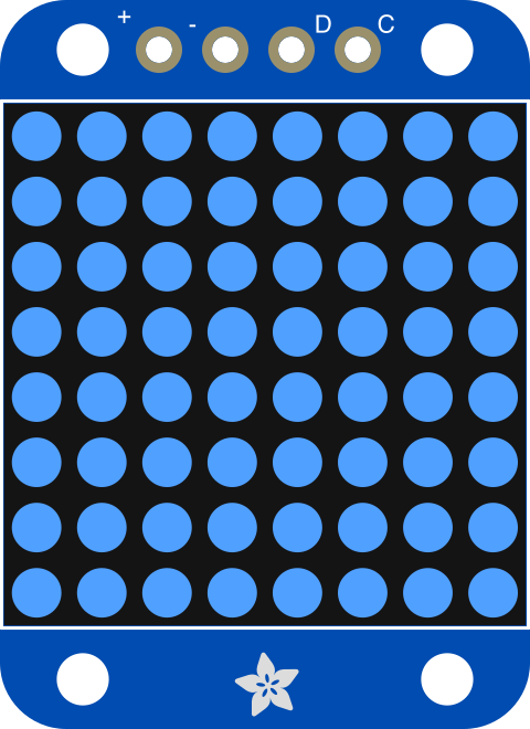
 Design with Adafruit Mini 8x8 LED Matrix Backpack - Blue in Cirkit Designer
Introduction
The Adafruit Mini 8x8 LED Matrix Backpack - Blue (Manufacturer Part ID: 959) is a compact and versatile LED matrix driver designed for controlling an 8x8 LED matrix display. This module simplifies the process of creating visual displays by utilizing I2C communication, making it easy to integrate with microcontrollers such as Arduino, Raspberry Pi, and others. The backpack includes built-in memory for storing images and animations, enabling smooth and efficient operation.
Explore Projects Built with Adafruit Mini 8x8 LED Matrix Backpack - Blue
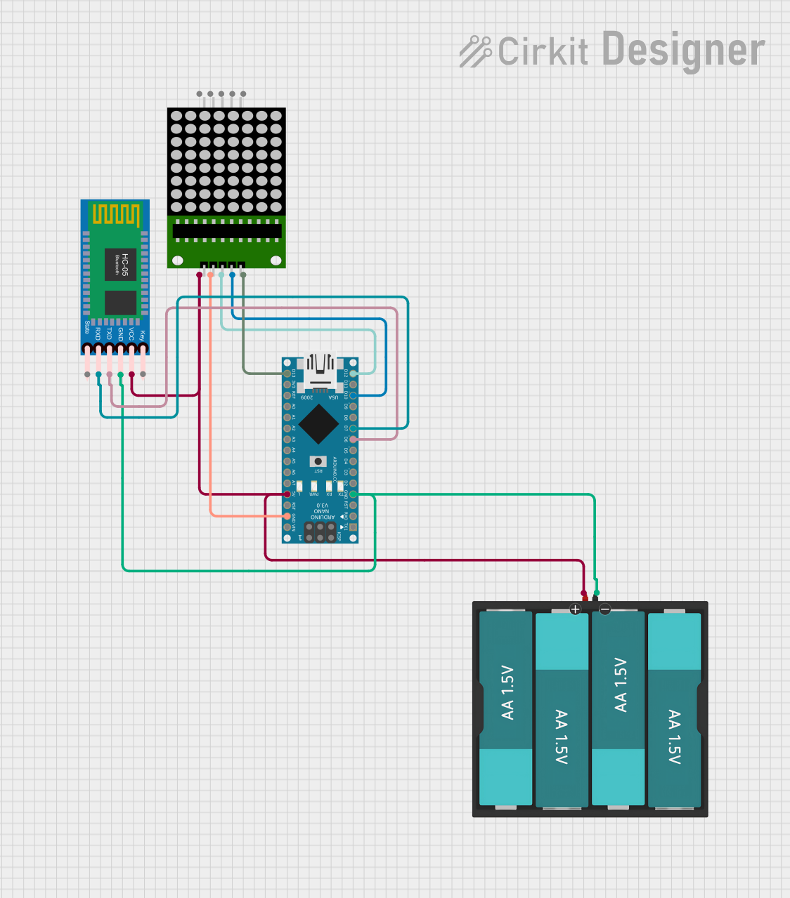 Open Project in Cirkit Designer
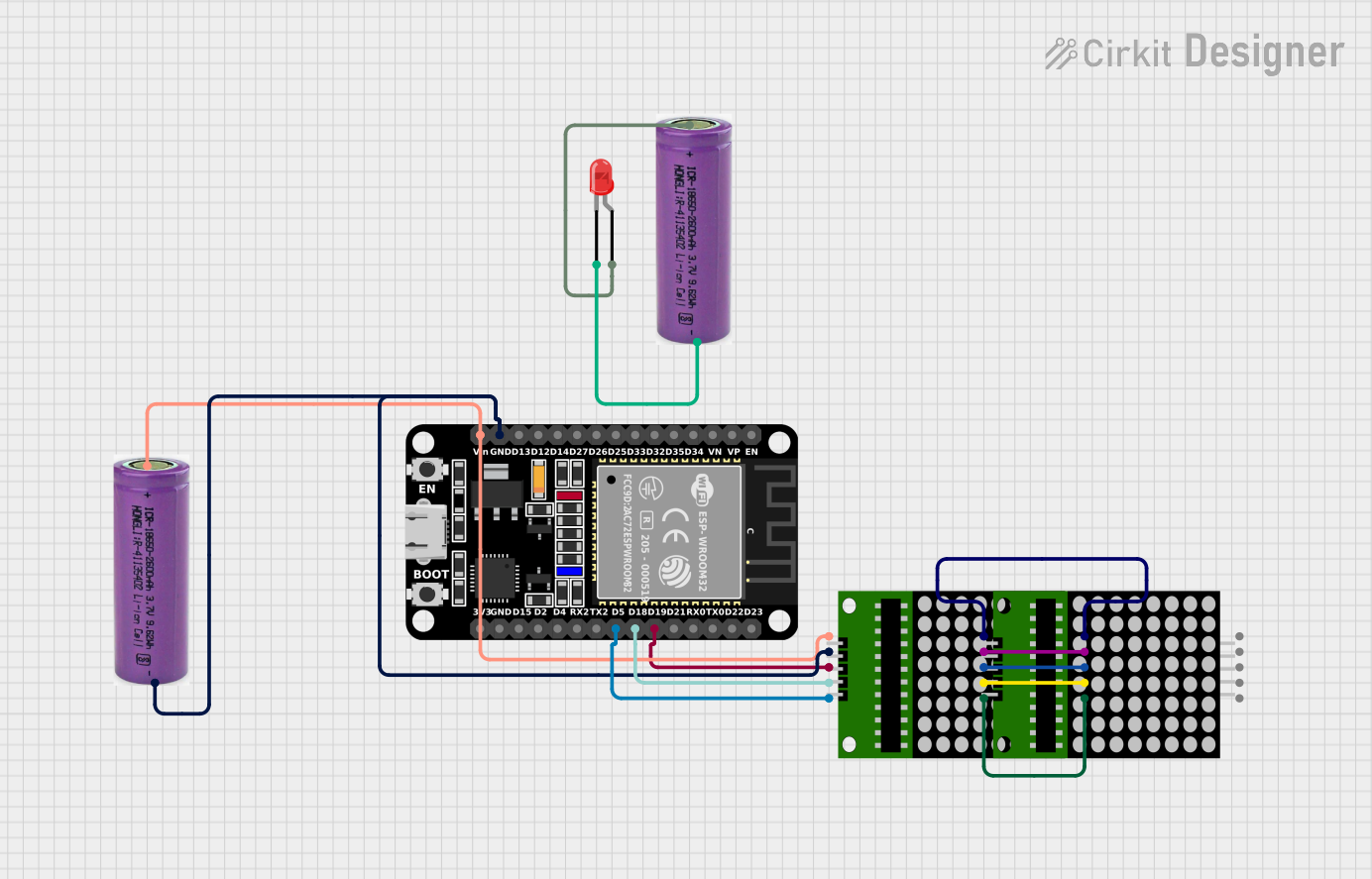 Open Project in Cirkit Designer
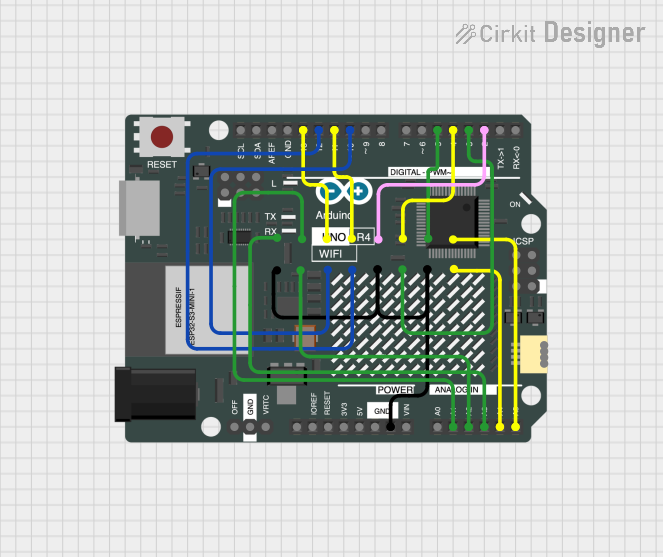 Open Project in Cirkit Designer
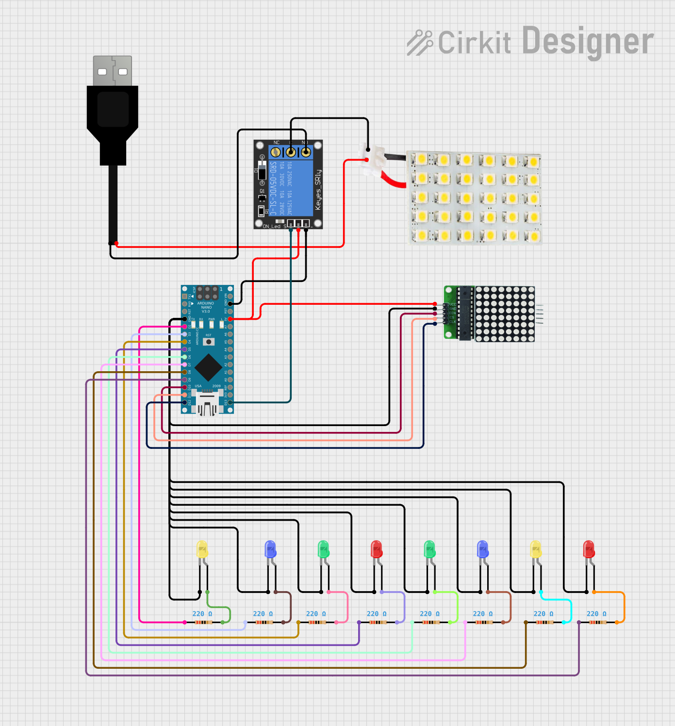 Open Project in Cirkit Designer
Explore Projects Built with Adafruit Mini 8x8 LED Matrix Backpack - Blue
Open Project in Cirkit DesignerOpen Project in Cirkit DesignerOpen Project in Cirkit DesignerOpen Project in Cirkit DesignerCommon Applications
- Visual indicators and status displays
- Scrolling text or animations
- Simple games and interactive projects
- Educational tools for learning about LED matrices and I2C communication
Technical Specifications
Key Technical Details
| Parameter | Value |
|---|---|
| Manufacturer | Adafruit |
| Manufacturer Part ID | 959 |
| LED Matrix Dimensions | 8x8 (64 LEDs) |
| LED Color | Blue |
| Communication Protocol | I2C |
| Operating Voltage | 5V DC |
| Current Consumption | ~20mA (varies with LED usage) |
| I2C Address Range | 0x70 to 0x77 (configurable) |
| Dimensions | 1.2" x 1.2" x 0.2" (30mm x 30mm x 5mm) |
| Weight | ~4g |
Pin Configuration and Descriptions
The backpack has a 4-pin header for I2C communication and power input. Below is the pinout:
| Pin Name | Description |
|---|---|
| VIN | Power input (5V DC) |
| GND | Ground |
| SDA | I2C data line |
| SCL | I2C clock line |
Usage Instructions
How to Use the Component in a Circuit
Wiring the Matrix Backpack:
- Connect the
VINpin to the 5V output of your microcontroller. - Connect the
GNDpin to the ground of your microcontroller. - Connect the
SDApin to the I2C data line of your microcontroller. - Connect the
SCLpin to the I2C clock line of your microcontroller.
- Connect the
Installing Required Libraries:
- Download and install the Adafruit LED Backpack library and the Adafruit GFX library from the Arduino Library Manager.
Configuring the I2C Address:
- The default I2C address is
0x70. If you need to change it, solder the address jumpers on the back of the board to set a new address (refer to the Adafruit guide for details).
- The default I2C address is
Programming the Matrix:
- Use the Adafruit GFX library to create text, shapes, or animations on the matrix.
Example Code for Arduino UNO
Below is an example code snippet to display a simple animation on the LED matrix:
#include <Wire.h>
#include <Adafruit_GFX.h>
#include <Adafruit_LEDBackpack.h>

// Create an instance of the LED matrix
Adafruit_8x8matrix matrix = Adafruit_8x8matrix();

void setup() {
  // Initialize the matrix
  matrix.begin(0x70); // Default I2C address is 0x70
  matrix.clear();
  matrix.writeDisplay();
}

void loop() {
  // Display a simple animation
  for (int i = 0; i < 8; i++) {
    matrix.clear();
    matrix.drawPixel(i, i, LED_ON); // Light up diagonal pixels
    matrix.writeDisplay();
    delay(200); // Wait for 200ms
  }
}
Important Considerations and Best Practices
- Ensure the I2C pull-up resistors are enabled on your microcontroller or added externally if needed.
- Avoid exceeding the maximum current rating of the module to prevent damage.
- Use a regulated 5V power supply to ensure stable operation.
- If using multiple backpacks, configure unique I2C addresses for each.
Troubleshooting and FAQs
Common Issues and Solutions
The LED matrix does not light up:
- Verify all connections (VIN, GND, SDA, SCL) are secure and correct.
- Ensure the I2C address in your code matches the address configured on the backpack.
- Check that the power supply provides a stable 5V.
Flickering or dim LEDs:
- Ensure the power supply can provide sufficient current for the LEDs.
- Check for loose or poor connections in the circuit.
I2C communication errors:
- Confirm that the SDA and SCL lines are connected to the correct pins on your microcontroller.
- Check for conflicting I2C addresses if multiple devices are connected.
Unable to upload code to Arduino:
- Disconnect the SDA and SCL lines temporarily while uploading the code, as some I2C devices can interfere with the upload process.
FAQs
Q: Can I use this module with a 3.3V microcontroller?
A: Yes, the module is compatible with 3.3V logic levels, but you must still provide a 5V power supply to the VIN pin.
Q: How do I chain multiple LED backpacks together?
A: Connect the VIN, GND, SDA, and SCL pins of all backpacks in parallel. Assign a unique I2C address to each backpack by configuring the address jumpers.
Q: Can I display custom graphics on the matrix?
A: Yes, you can use the Adafruit GFX library to draw custom shapes, text, and animations.
Q: What is the maximum number of backpacks I can connect?
A: You can connect up to 8 backpacks on the same I2C bus, as there are 8 configurable I2C addresses (0x70 to 0x77).
This concludes the documentation for the Adafruit Mini 8x8 LED Matrix Backpack - Blue. For further assistance, refer to the official Adafruit guide or community forums.