How to Use Connection Node 1pin: Examples, Pinouts, and Specs

Introduction
The Connection Node 1pin is a versatile electronic component designed to facilitate single-point electrical connections in a circuit. Its simple yet effective design allows for easy integration into modular systems, making it an essential component for prototyping, testing, and permanent installations. This component is ideal for connecting wires, modules, or other circuit elements in a reliable and efficient manner.
Explore Projects Built with Connection Node 1pin


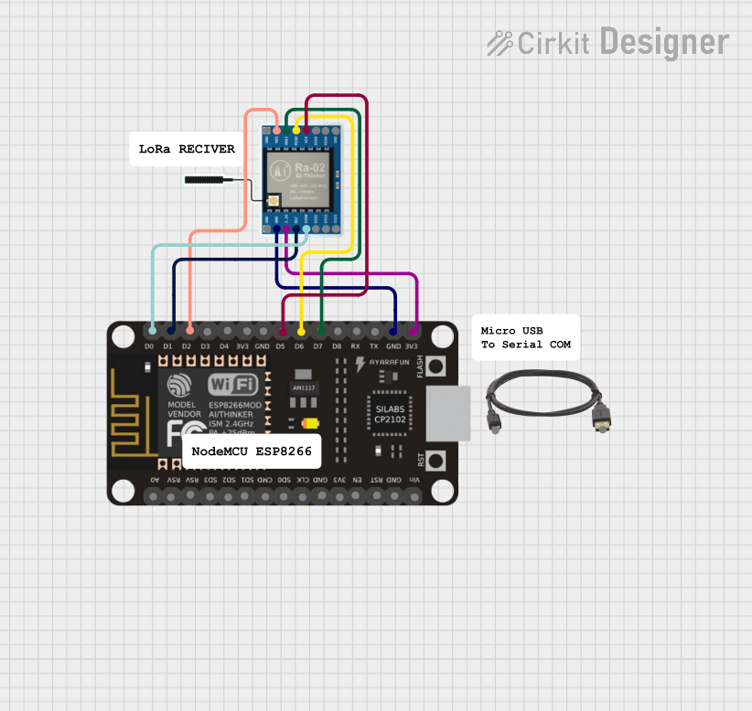
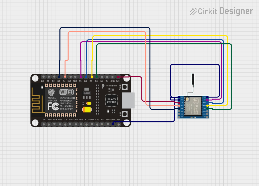
Explore Projects Built with Connection Node 1pin
Common Applications and Use Cases
- Prototyping and breadboarding circuits
- Establishing modular connections in electronic systems
- Extending or branching electrical connections
- Connecting sensors, actuators, or other components to microcontrollers
- Repairing or modifying existing circuits
Technical Specifications
The Connection Node 1pin is a passive component with no active electronic properties. Below are its key specifications:
| Parameter | Value |
|---|---|
| Material | Copper (conductive core) with optional plating (e.g., tin or gold) |
| Maximum Current Rating | 5A |
| Maximum Voltage Rating | 50V DC |
| Pin Diameter | 1.0 mm |
| Insulation Material | Optional (varies by design) |
| Operating Temperature | -40°C to +85°C |
Pin Configuration and Descriptions
The Connection Node 1pin has a single pin for electrical connection. Below is the pin description:
| Pin Number | Description |
|---|---|
| 1 | Electrical connection point (signal or power) |
Usage Instructions
How to Use the Connection Node 1pin in a Circuit
- Identify the Connection Point: Determine where the Connection Node 1pin will be used in your circuit. It can serve as a junction for wires, a connection point for modules, or a pin for interfacing with a microcontroller.
- Insert or Solder: Depending on your application:
- For breadboards or prototyping, insert the pin into the desired hole.
- For permanent installations, solder the pin to a PCB or wire.
- Connect Wires or Components: Attach wires or components to the pin using solder or connectors, ensuring a secure and reliable connection.
- Test the Circuit: Verify the electrical connection using a multimeter or by powering the circuit.
Important Considerations and Best Practices
- Avoid Overloading: Ensure the current and voltage do not exceed the maximum ratings (5A and 50V DC).
- Secure Connections: For long-term use, solder the pin to prevent loose connections.
- Insulation: If the pin is exposed, consider using heat shrink tubing or other insulation to prevent short circuits.
- Corrosion Protection: If used in humid or corrosive environments, select a version with gold or tin plating for better durability.
Example: Connecting to an Arduino UNO
The Connection Node 1pin can be used to interface sensors or modules with an Arduino UNO. Below is an example of connecting a sensor's signal pin to an Arduino's analog input using the Connection Node 1pin.
Arduino Code Example
// Example: Reading an analog sensor value connected via Connection Node 1pin
// The sensor's signal pin is connected to Arduino pin A0.

const int sensorPin = A0; // Define the analog input pin
int sensorValue = 0;      // Variable to store the sensor reading

void setup() {
  Serial.begin(9600); // Initialize serial communication at 9600 baud
}

void loop() {
  sensorValue = analogRead(sensorPin); // Read the sensor value
  Serial.print("Sensor Value: ");      // Print the sensor value to the serial monitor
  Serial.println(sensorValue);
  delay(500); // Wait for 500ms before the next reading
}
Troubleshooting and FAQs
Common Issues Users Might Face
Loose Connections:
- Problem: The pin is not securely connected, causing intermittent signals.
- Solution: Solder the pin or use a secure connector to ensure a stable connection.
Short Circuits:
- Problem: Exposed pins come into contact with other conductive surfaces.
- Solution: Use insulation (e.g., heat shrink tubing) to cover exposed areas.
Corrosion or Oxidation:
- Problem: The pin becomes corroded, leading to poor conductivity.
- Solution: Use a version with corrosion-resistant plating (e.g., gold or tin).
Overloading:
- Problem: Exceeding the current or voltage rating damages the pin or connected components.
- Solution: Verify the circuit's current and voltage requirements before use.
Solutions and Tips for Troubleshooting
- Use a multimeter to check for continuity and ensure the pin is properly connected.
- Inspect the pin for physical damage or corrosion and replace it if necessary.
- Double-check the circuit design to ensure the pin is used within its specified ratings.
By following these guidelines, the Connection Node 1pin can be effectively utilized in a wide range of electronic applications.