How to Use 5 IR Array: Examples, Pinouts, and Specs
Introduction
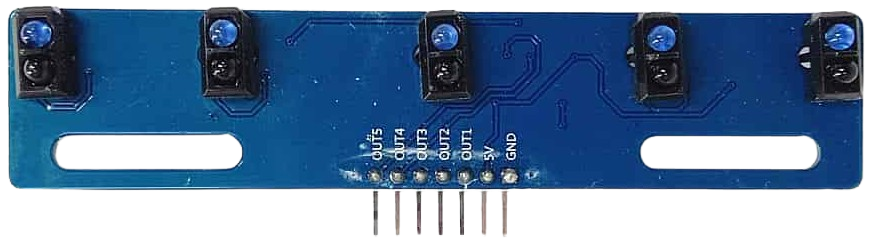
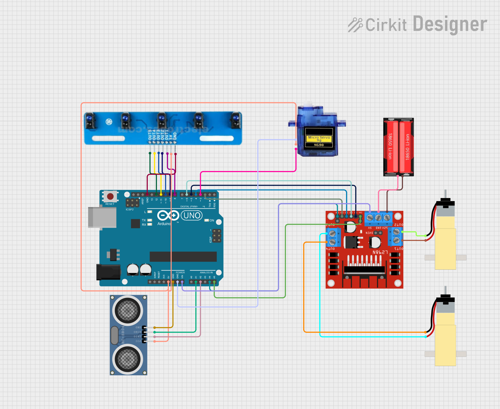
The 5 IR Array is a compact module consisting of five infrared (IR) sensors arranged in a linear configuration. Each sensor in the array is capable of detecting infrared radiation, making it ideal for applications such as heat detection, motion sensing, and proximity measurement. This component is widely used in robotics, automation systems, and line-following robots due to its ability to detect obstacles and environmental changes with precision.
Explore Projects Built with 5 IR Array
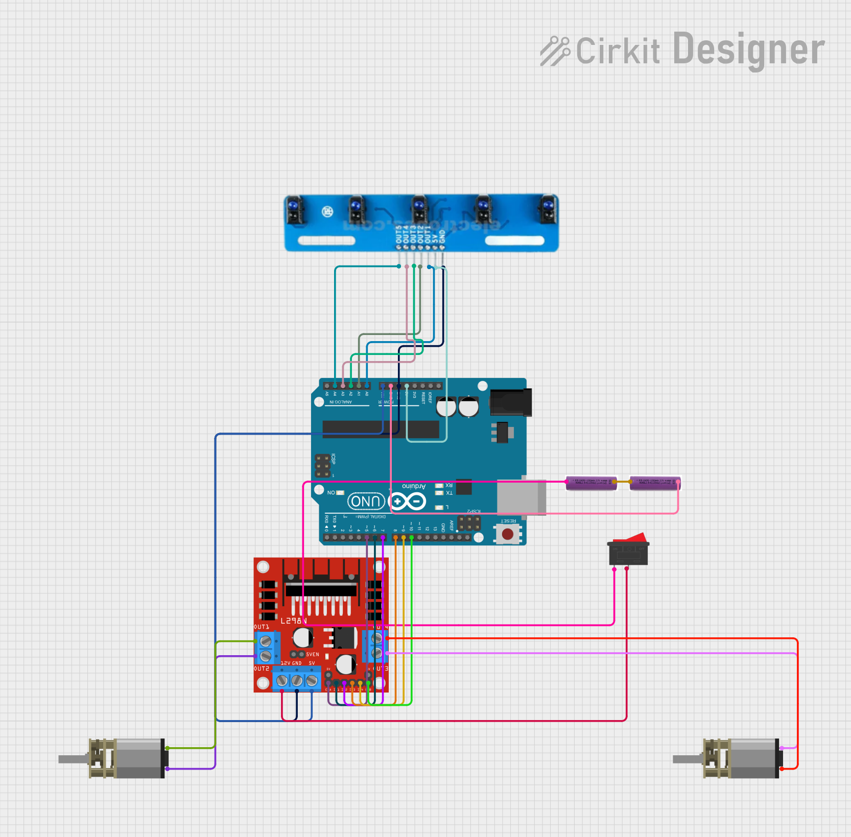
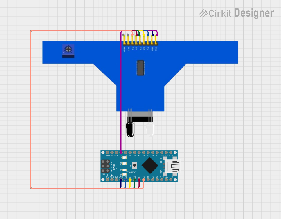
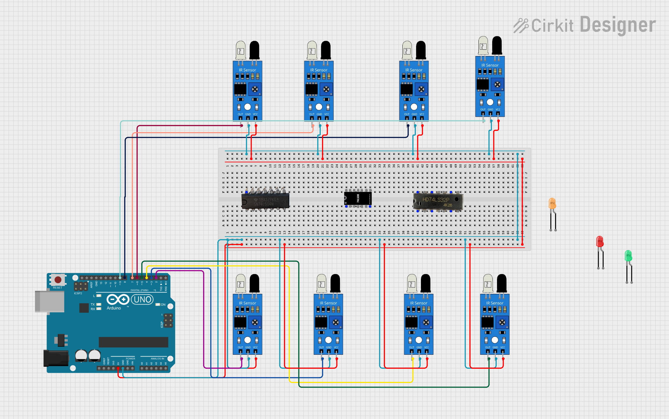
Explore Projects Built with 5 IR Array
Common Applications:
- Line-following robots
- Obstacle detection in robotics
- Proximity sensing in automation systems
- Environmental heat detection
- Object tracking and motion sensing
Technical Specifications
The following table outlines the key technical details of the 5 IR Array:
| Parameter | Value |
|---|---|
| Operating Voltage | 3.3V to 5V |
| Operating Current | 20mA (typical) |
| Detection Range | 2 cm to 30 cm (depending on object) |
| Output Type | Digital (High/Low) |
| Sensor Type | Infrared (IR) |
| Dimensions | Varies by manufacturer (e.g., 50mm x 10mm) |
Pin Configuration
The 5 IR Array typically has the following pin configuration:
| Pin Name | Description |
|---|---|
| VCC | Power supply input (3.3V to 5V) |
| GND | Ground connection |
| OUT1 | Digital output from IR sensor 1 |
| OUT2 | Digital output from IR sensor 2 |
| OUT3 | Digital output from IR sensor 3 |
| OUT4 | Digital output from IR sensor 4 |
| OUT5 | Digital output from IR sensor 5 |
Usage Instructions
How to Use the 5 IR Array in a Circuit
- Power the Module: Connect the
VCCpin to a 3.3V or 5V power source and theGNDpin to the ground of your circuit. - Connect Outputs: Each sensor in the array has a dedicated output pin (
OUT1toOUT5). Connect these pins to the input pins of a microcontroller (e.g., Arduino UNO) or other processing units. - Read Sensor Data: The output pins provide a digital signal:
- High (1): No object detected or object out of range.
- Low (0): Object detected within the sensor's range.
Important Considerations
- Ambient Light: IR sensors can be affected by strong ambient light. Use the array in controlled lighting conditions for optimal performance.
- Object Reflectivity: The detection range may vary depending on the reflectivity of the object. Highly reflective surfaces are easier to detect.
- Mounting: Ensure the array is mounted securely and aligned properly for accurate detection.
Example: Using the 5 IR Array with Arduino UNO
Below is an example code snippet to read data from the 5 IR Array using an Arduino UNO:
// Define the pins connected to the 5 IR Array
const int sensorPins[5] = {2, 3, 4, 5, 6}; // OUT1 to OUT5 connected to pins 2-6

void setup() {
  // Initialize serial communication for debugging
  Serial.begin(9600);

  // Set sensor pins as input
  for (int i = 0; i < 5; i++) {
    pinMode(sensorPins[i], INPUT);
  }
}

void loop() {
  // Read and print the state of each sensor
  for (int i = 0; i < 5; i++) {
    int sensorState = digitalRead(sensorPins[i]); // Read digital signal
    Serial.print("Sensor ");
    Serial.print(i + 1);
    Serial.print(": ");
    Serial.println(sensorState ? "No Object" : "Object Detected");
  }
  delay(500); // Wait for 500ms before the next reading
}
Best Practices
- Use pull-up or pull-down resistors if required to stabilize the output signals.
- Avoid placing the array too close to reflective surfaces to prevent false readings.
- Regularly clean the IR sensors to remove dust or debris that may interfere with detection.
Troubleshooting and FAQs
Common Issues and Solutions
No Output from Sensors:
- Cause: Incorrect power supply or loose connections.
- Solution: Verify that the
VCCandGNDpins are connected properly and the power supply voltage is within the specified range.
False Readings in Bright Light:
- Cause: Ambient light interference.
- Solution: Use the array in a controlled lighting environment or add an IR filter to the sensors.
Inconsistent Detection Range:
- Cause: Object reflectivity or sensor misalignment.
- Solution: Test with different objects and ensure the array is properly aligned.
All Sensors Always High or Low:
- Cause: Faulty module or incorrect wiring.
- Solution: Check the wiring and test the module with a multimeter or another microcontroller.
FAQs
Q1: Can the 5 IR Array detect transparent objects?
A1: Transparent objects, such as glass, may not reflect enough IR radiation for detection. Use alternative sensors for such applications.
Q2: What is the maximum detection range of the 5 IR Array?
A2: The detection range is typically 2 cm to 30 cm, but it depends on the object's size, shape, and reflectivity.
Q3: Can I use the 5 IR Array with a 3.3V microcontroller?
A3: Yes, the array is compatible with both 3.3V and 5V systems. Ensure the output signals are within the input voltage range of your microcontroller.
Q4: How do I clean the sensors?
A4: Use a soft, lint-free cloth to gently wipe the sensor surfaces. Avoid using liquids or abrasive materials.
By following this documentation, you can effectively integrate the 5 IR Array into your projects and troubleshoot common issues with ease.