
How to Use 3.5mm Audio Jack: Examples, Pinouts, and Specs
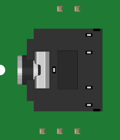
 Design with 3.5mm Audio Jack in Cirkit Designer
Introduction
The 3.5mm Audio Jack (Manufacturer: SparkFun, Part ID: PRT-08032) is a widely used connector for audio devices. It is designed to transmit audio signals, typically in stereo, and is compatible with a variety of devices such as headphones, speakers, microphones, and audio amplifiers. This component is ideal for projects requiring audio input or output functionality.
Explore Projects Built with 3.5mm Audio Jack
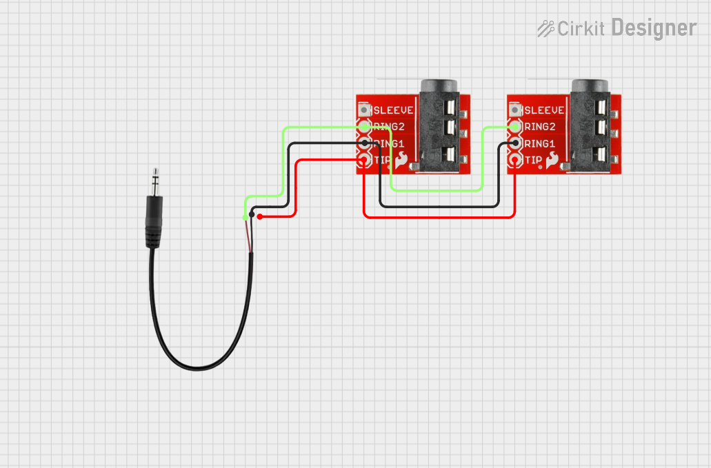 Open Project in Cirkit Designer
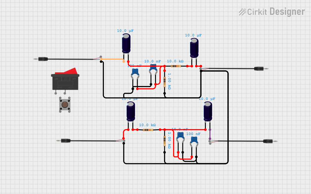 Open Project in Cirkit Designer
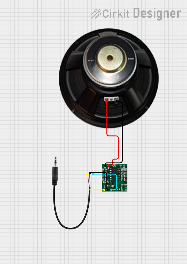 Open Project in Cirkit Designer
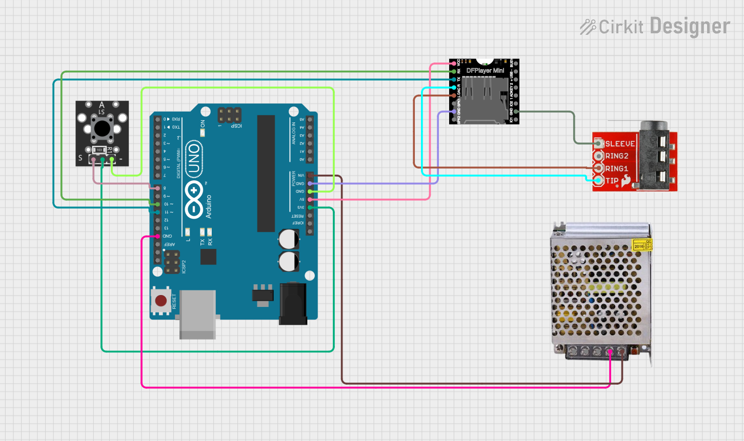 Open Project in Cirkit Designer
Explore Projects Built with 3.5mm Audio Jack
Open Project in Cirkit DesignerOpen Project in Cirkit DesignerOpen Project in Cirkit DesignerOpen Project in Cirkit DesignerCommon Applications and Use Cases
- Connecting headphones or speakers to audio devices
- Audio input/output for microcontroller projects
- Integration into audio amplifiers or mixers
- DIY audio equipment and repair projects
- Prototyping audio circuits
Technical Specifications
The following table outlines the key technical details of the SparkFun 3.5mm Audio Jack (PRT-08032):
| Parameter | Specification |
|---|---|
| Connector Type | 3.5mm Stereo Audio Jack |
| Number of Contacts | 5 (Tip, Ring 1, Ring 2, Sleeve, Shield) |
| Mounting Style | Through-Hole |
| Voltage Rating | 12V DC (maximum) |
| Current Rating | 1A (maximum) |
| Contact Resistance | ≤ 50 mΩ |
| Insulation Resistance | ≥ 100 MΩ |
| Operating Temperature | -25°C to +85°C |
| Dimensions | 14.5mm x 6.5mm x 6.5mm |
Pin Configuration and Descriptions
The 3.5mm audio jack has five pins, which are typically used for stereo audio signals and ground connections. The pinout is as follows:
| Pin | Name | Description |
|---|---|---|
| 1 | Tip (T) | Left audio channel (L) |
| 2 | Ring 1 (R1) | Right audio channel (R) |
| 3 | Ring 2 (R2) | Optional microphone input or additional ground |
| 4 | Sleeve (S) | Ground (common for audio signals) |
| 5 | Shield | Chassis ground or additional shielding |
Usage Instructions
How to Use the Component in a Circuit
- Identify the Pins: Refer to the pin configuration table to identify the correct pins for your application.
- Soldering: Secure the audio jack to your PCB using the through-hole mounting points. Ensure proper soldering for reliable connections.
- Connect Audio Signals:
- Connect the Tip (T) pin to the left audio channel output of your circuit.
- Connect the Ring 1 (R1) pin to the right audio channel output.
- If using a microphone, connect the Ring 2 (R2) pin to the microphone input.
- Connect the Sleeve (S) pin to the ground of your circuit.
- Test the Connections: Use a multimeter to verify continuity and ensure there are no short circuits.
Important Considerations and Best Practices
- Signal Integrity: Use shielded cables to minimize noise and interference in audio signals.
- Voltage and Current Ratings: Do not exceed the specified voltage (12V DC) or current (1A) ratings to avoid damage.
- Mounting: Ensure the jack is securely mounted to prevent mechanical stress on the solder joints.
- Compatibility: Verify that the connected device uses a standard 3.5mm stereo plug.
Example: Connecting to an Arduino UNO
The 3.5mm audio jack can be used to interface audio signals with an Arduino UNO. Below is an example of reading an audio signal from the jack's left channel:
// Example: Reading audio signal from the 3.5mm audio jack
// Connect the Tip (T) pin to Arduino analog pin A0
// Connect the Sleeve (S) pin to Arduino GND

const int audioPin = A0; // Analog pin connected to the Tip (left channel)
int audioValue = 0;      // Variable to store the audio signal value

void setup() {
  Serial.begin(9600); // Initialize serial communication
}

void loop() {
  audioValue = analogRead(audioPin); // Read the audio signal
  Serial.println(audioValue);       // Print the signal value to the Serial Monitor
  delay(10);                        // Small delay for stability
}
Note: The audio signal must be within the Arduino's input voltage range (0-5V). Use a voltage divider or capacitor coupling if necessary.
Troubleshooting and FAQs
Common Issues Users Might Face
No Audio Output:
- Cause: Incorrect pin connections or poor soldering.
- Solution: Double-check the pinout and ensure all connections are secure.
Noise or Interference:
- Cause: Unshielded cables or improper grounding.
- Solution: Use shielded cables and ensure the ground connections are solid.
Audio Signal Too Weak:
- Cause: Low signal amplitude from the source.
- Solution: Use an audio amplifier circuit to boost the signal.
Short Circuits:
- Cause: Solder bridges between pins.
- Solution: Inspect the solder joints and remove any accidental bridges.
Solutions and Tips for Troubleshooting
- Use a multimeter to verify continuity and check for short circuits.
- Test the audio jack with a known working audio source and output device to isolate the issue.
- If using with a microcontroller, ensure the audio signal is within the acceptable voltage range.
By following this documentation, you can effectively integrate the SparkFun 3.5mm Audio Jack (PRT-08032) into your audio projects with confidence.