How to Use C1815: Examples, Pinouts, and Specs
Introduction
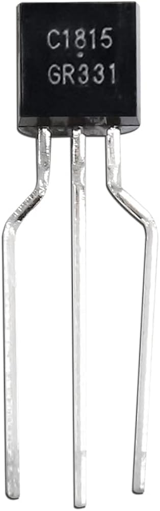
The C1815 is a general-purpose NPN bipolar junction transistor (BJT) widely used in electronic circuits for amplification and switching applications. It is designed for low to medium power operations, making it a versatile component in various projects. With a maximum collector current of 800 mA and a maximum collector-emitter voltage of 50 V, the C1815 is suitable for audio amplification, signal processing, and small motor control.
Explore Projects Built with C1815

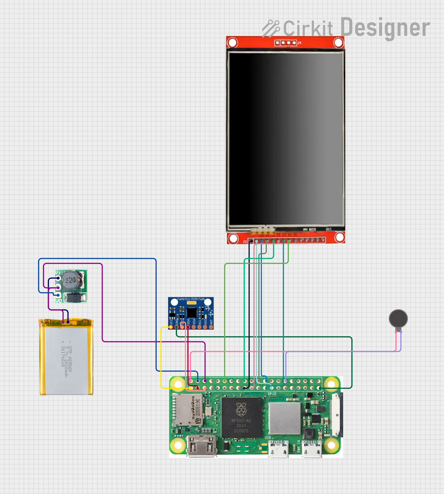
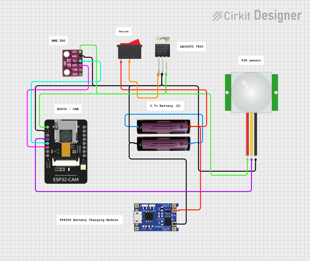

Explore Projects Built with C1815
Common Applications
- Audio signal amplification
- Low-power switching circuits
- Oscillator circuits
- Small DC motor drivers
- General-purpose electronic projects
Technical Specifications
Below are the key technical details of the C1815 transistor:
| Parameter | Value |
|---|---|
| Transistor Type | NPN |
| Maximum Collector Current (Ic) | 800 mA |
| Maximum Collector-Emitter Voltage (Vce) | 50 V |
| Maximum Collector-Base Voltage (Vcb) | 60 V |
| Maximum Emitter-Base Voltage (Veb) | 5 V |
| DC Current Gain (hFE) | 70 to 700 (varies by model) |
| Power Dissipation (Pc) | 400 mW |
| Transition Frequency (ft) | 80 MHz |
| Package Type | TO-92 |
Pin Configuration
The C1815 transistor comes in a TO-92 package with three pins. The pinout is as follows:
| Pin Number | Pin Name | Description |
|---|---|---|
| 1 | Emitter (E) | Current flows out of this pin |
| 2 | Base (B) | Controls the transistor's operation |
| 3 | Collector (C) | Current flows into this pin |
The pinout is typically viewed with the flat side of the TO-92 package facing you.
Usage Instructions
Using the C1815 in a Circuit
Amplification: To use the C1815 as an amplifier:
- Connect the base pin to the input signal through a current-limiting resistor.
- The collector is connected to the positive voltage supply through a load (e.g., a resistor or speaker).
- The emitter is connected to ground.
- Ensure the base current is sufficient to drive the transistor into active mode.
Switching: To use the C1815 as a switch:
- Connect the load (e.g., an LED or motor) between the positive voltage supply and the collector.
- Use a resistor to limit the base current and connect the base to a control signal.
- The emitter is connected to ground.
- Apply a high signal to the base to turn the transistor on, allowing current to flow through the load.
Important Considerations
- Base Resistor: Always use a resistor in series with the base to limit the base current and prevent damage to the transistor.
- Power Dissipation: Ensure the power dissipation does not exceed 400 mW to avoid overheating.
- Voltage Ratings: Do not exceed the maximum voltage ratings (Vce, Vcb, Veb) to prevent breakdown.
Example: Controlling an LED with Arduino UNO
Below is an example of using the C1815 transistor to control an LED with an Arduino UNO:
// Define the pin connected to the transistor's base
const int transistorBasePin = 9; // Digital pin 9 on Arduino

void setup() {
  pinMode(transistorBasePin, OUTPUT); // Set the pin as an output
}

void loop() {
  digitalWrite(transistorBasePin, HIGH); // Turn on the transistor (LED ON)
  delay(1000); // Wait for 1 second
  digitalWrite(transistorBasePin, LOW);  // Turn off the transistor (LED OFF)
  delay(1000); // Wait for 1 second
}
Circuit Connections:
- Connect the emitter of the C1815 to ground.
- Connect the collector to one terminal of the LED. The other terminal of the LED is connected to a current-limiting resistor, which is then connected to the positive voltage supply.
- Connect the base to Arduino pin 9 through a 1 kΩ resistor.
Troubleshooting and FAQs
Common Issues
Transistor Not Switching Properly:
- Check if the base resistor value is appropriate. A very high resistance may not provide enough base current.
- Ensure the control signal voltage is sufficient to turn the transistor on (typically 0.7 V or higher for the base-emitter junction).
Overheating:
- Verify that the collector current does not exceed 800 mA.
- Ensure the power dissipation is within the 400 mW limit.
No Output Signal:
- Check all connections, especially the base resistor and load connections.
- Ensure the transistor is not damaged by testing it with a multimeter.
FAQs
Q: Can I use the C1815 for high-power applications?
A: No, the C1815 is designed for low to medium power applications. For high-power circuits, consider using a power transistor like the TIP120.
Q: What is the typical base resistor value for the C1815?
A: The base resistor value depends on the input signal and desired base current. A common value is 1 kΩ for most applications.
Q: How do I test if my C1815 transistor is working?
A: Use a multimeter in diode mode to check the base-emitter and base-collector junctions. A forward voltage drop of approximately 0.6-0.7 V indicates a functional junction.
By following this documentation, you can effectively use the C1815 transistor in your electronic projects.