How to Use md20b: Examples, Pinouts, and Specs
Introduction
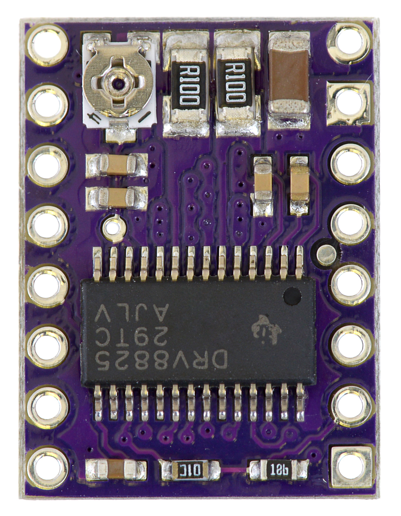
The MD20B, manufactured by Pololu, is a compact and efficient DC motor driver designed to control the speed and direction of DC motors. It is equipped with built-in protection features, including overcurrent and thermal overload safeguards, ensuring reliable operation in demanding environments. This motor driver is ideal for robotics, automation systems, and other applications requiring precise motor control.
Explore Projects Built with md20b
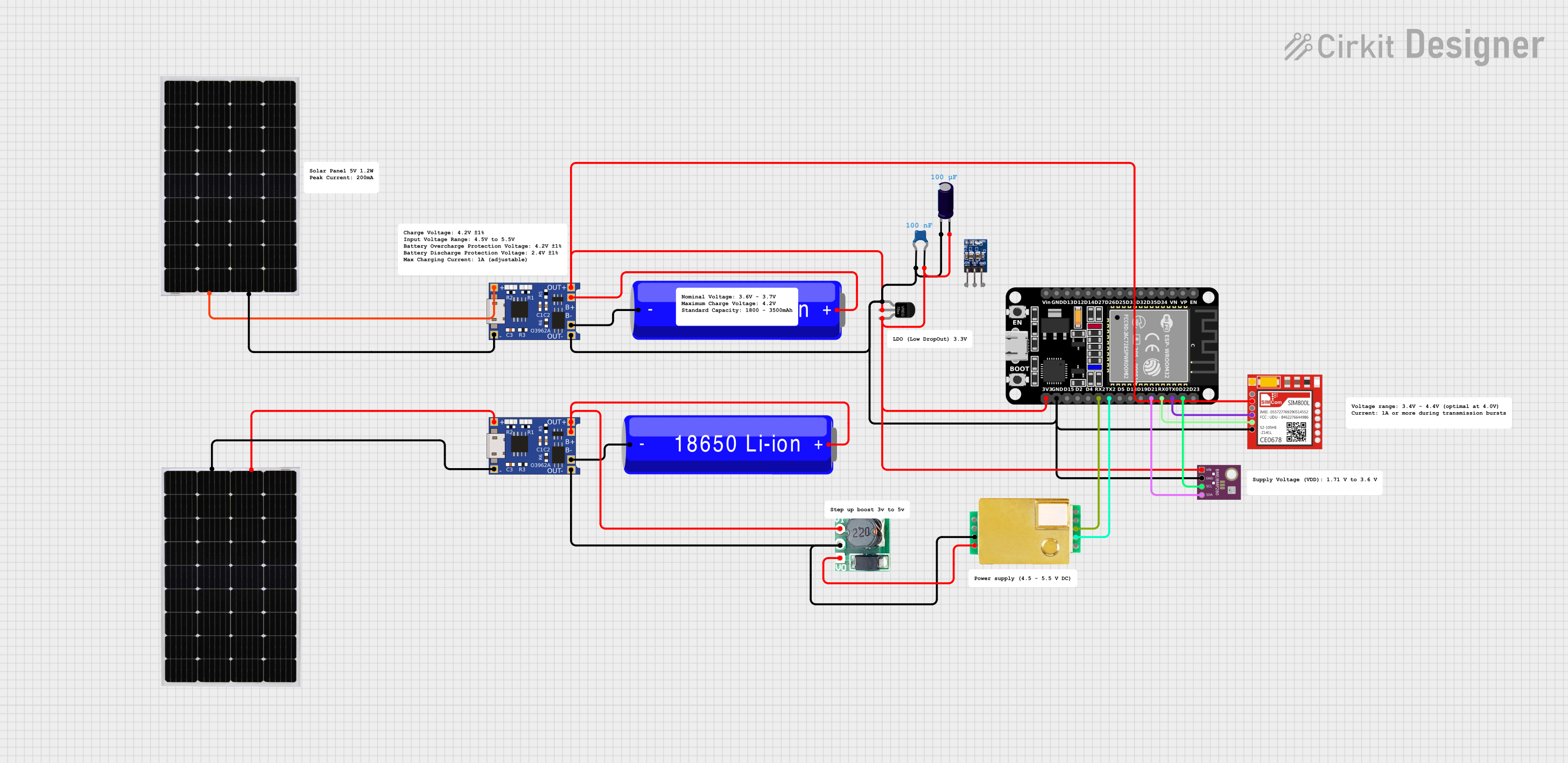


Explore Projects Built with md20b
Common Applications
- Robotics and mechatronics projects
- Automated conveyor systems
- Remote-controlled vehicles
- Industrial automation
- Educational electronics projects
Technical Specifications
The MD20B motor driver is designed to handle a wide range of DC motor control tasks. Below are its key technical details:
| Parameter | Value |
|---|---|
| Operating Voltage | 6 V to 30 V |
| Continuous Output Current | 20 A |
| Peak Output Current | 30 A (for short durations) |
| Control Interface | PWM (Pulse Width Modulation) |
| Logic Voltage Range | 3.3 V to 5 V |
| Thermal Shutdown | Yes |
| Overcurrent Protection | Yes |
| Dimensions | 1.5" x 1.2" x 0.5" (approx.) |
| Weight | 10 g |
Pin Configuration and Descriptions
The MD20B features a simple pinout for easy integration into your circuits. Below is the pin configuration:
| Pin Name | Type | Description |
|---|---|---|
| VIN | Power Input | Connect to the positive terminal of the motor power supply (6 V to 30 V). |
| GND | Power Ground | Connect to the ground of the motor power supply and control circuit. |
| M1+ | Motor Output | Connect to one terminal of the DC motor. |
| M1- | Motor Output | Connect to the other terminal of the DC motor. |
| PWM | Input Signal | Accepts a PWM signal to control motor speed (3.3 V or 5 V logic). |
| DIR | Input Signal | Sets the motor direction: HIGH for forward, LOW for reverse. |
| EN | Input Signal | Enable pin: HIGH to enable the motor driver, LOW to disable it. |
| FAULT | Output Signal | Active LOW signal indicating a fault condition (e.g., overcurrent or overheat). |
Usage Instructions
How to Use the MD20B in a Circuit
- Power Supply: Connect the VIN and GND pins to a DC power supply within the range of 6 V to 30 V. Ensure the power supply can provide sufficient current for your motor.
- Motor Connection: Connect the motor terminals to the M1+ and M1- pins.
- Control Signals:
- Connect the PWM pin to a microcontroller or PWM signal generator to control motor speed.
- Use the DIR pin to set the motor's direction (HIGH for forward, LOW for reverse).
- The EN pin must be set HIGH to enable the motor driver.
- Fault Monitoring: Optionally, connect the FAULT pin to a microcontroller input to monitor fault conditions.
Important Considerations
- Heat Dissipation: The MD20B may generate heat during operation. Ensure adequate ventilation or use a heatsink if operating at high currents for extended periods.
- Current Limits: Do not exceed the continuous current rating of 20 A to avoid damage.
- PWM Frequency: Use a PWM frequency between 1 kHz and 20 kHz for optimal performance.
- Logic Voltage: Ensure the control signals (PWM, DIR, EN) are within the 3.3 V to 5 V range.
Example: Using MD20B with Arduino UNO
Below is an example of how to control a DC motor using the MD20B and an Arduino UNO:
// Define pin connections
const int pwmPin = 9;  // PWM signal pin
const int dirPin = 8;  // Direction control pin
const int enPin = 7;   // Enable pin

void setup() {
  // Set pin modes
  pinMode(pwmPin, OUTPUT);
  pinMode(dirPin, OUTPUT);
  pinMode(enPin, OUTPUT);

  // Enable the motor driver
  digitalWrite(enPin, HIGH);
}

void loop() {
  // Set motor direction to forward
  digitalWrite(dirPin, HIGH);

  // Gradually increase motor speed
  for (int speed = 0; speed <= 255; speed++) {
    analogWrite(pwmPin, speed);  // Set PWM duty cycle
    delay(20);                   // Wait 20 ms
  }

  // Hold maximum speed for 2 seconds
  delay(2000);

  // Gradually decrease motor speed
  for (int speed = 255; speed >= 0; speed--) {
    analogWrite(pwmPin, speed);  // Set PWM duty cycle
    delay(20);                   // Wait 20 ms
  }

  // Set motor direction to reverse
  digitalWrite(dirPin, LOW);

  // Repeat the speed ramp-up and ramp-down
  for (int speed = 0; speed <= 255; speed++) {
    analogWrite(pwmPin, speed);
    delay(20);
  }
  delay(2000);
  for (int speed = 255; speed >= 0; speed--) {
    analogWrite(pwmPin, speed);
    delay(20);
  }
}
Troubleshooting and FAQs
Common Issues and Solutions
Motor Not Spinning:
- Ensure the EN pin is set HIGH to enable the motor driver.
- Verify that the power supply voltage is within the 6 V to 30 V range.
- Check the PWM signal and ensure it is being generated correctly.
Motor Spins in the Wrong Direction:
- Reverse the DIR pin signal (HIGH for forward, LOW for reverse).
- Alternatively, swap the motor connections on the M1+ and M1- pins.
Overheating:
- Ensure proper ventilation or attach a heatsink to the MD20B.
- Reduce the motor load or operating current if possible.
FAULT Pin is Active (LOW):
- Check for overcurrent or thermal overload conditions.
- Allow the driver to cool down if it has overheated.
- Verify that the motor is not drawing more than 20 A continuously.
FAQs
Q: Can I use the MD20B with a 3.3 V microcontroller?
A: Yes, the MD20B supports control signals in the 3.3 V to 5 V range, making it compatible with 3.3 V microcontrollers.
Q: What type of motors can the MD20B drive?
A: The MD20B is designed for brushed DC motors. It is not suitable for brushless motors.
Q: How do I reset the driver after a fault condition?
A: Remove the fault condition (e.g., reduce load or allow cooling), then toggle the EN pin LOW and HIGH to reset the driver.
Q: Can I use the MD20B for bidirectional motor control?
A: Yes, the DIR pin allows you to control the motor's direction, enabling bidirectional operation.