How to Use tsc3200: Examples, Pinouts, and Specs
Introduction
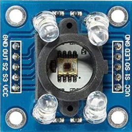
The TSC3200 is a programmable color sensor IC capable of detecting the intensity of red, green, and blue light. It uses an array of photodiodes and an integrated current-to-frequency converter to output a square wave with a frequency proportional to the intensity of the detected light. This makes it ideal for applications requiring color recognition and processing.
Explore Projects Built with tsc3200
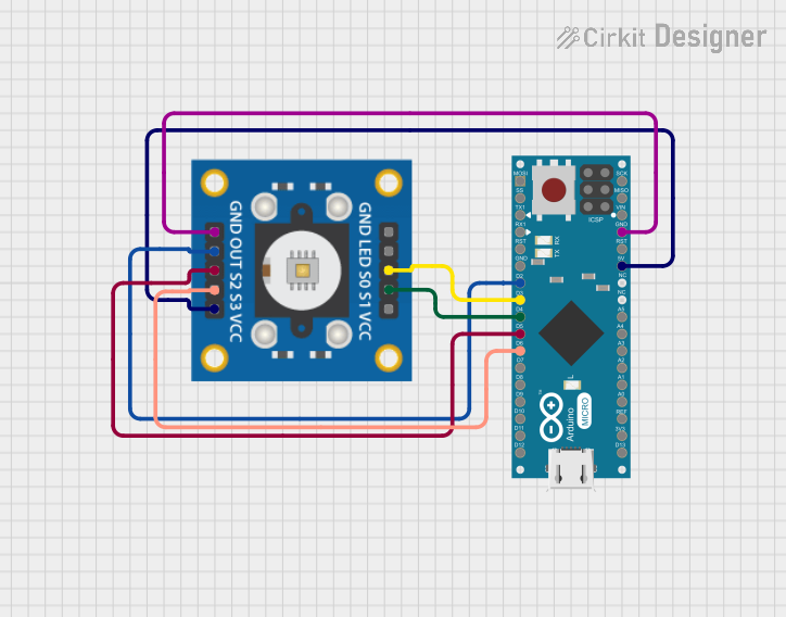

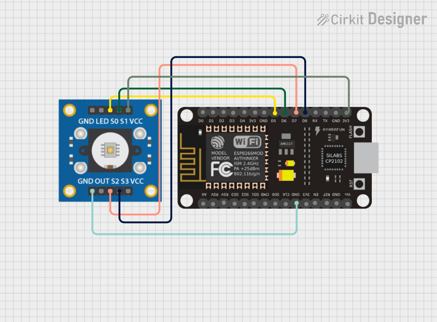
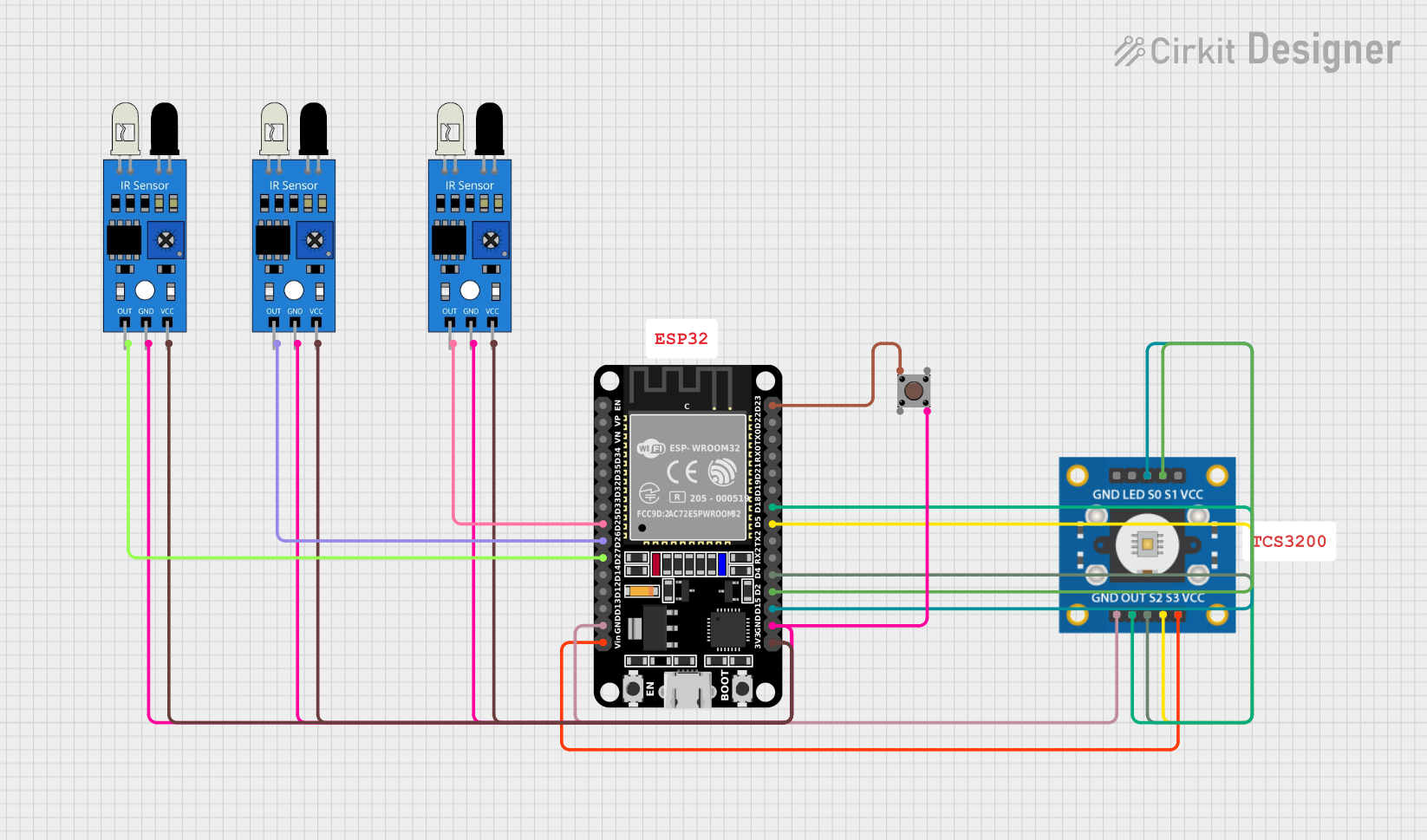
Explore Projects Built with tsc3200
Common Applications
- Robotics (e.g., line-following robots with color detection)
- Industrial automation (e.g., sorting objects by color)
- Consumer electronics (e.g., color calibration tools)
- Medical devices (e.g., colorimetric analysis)
- Educational projects and prototyping
Technical Specifications
The TSC3200 is a versatile and programmable sensor with the following key specifications:
| Parameter | Value |
|---|---|
| Supply Voltage (Vcc) | 2.7V to 5.5V |
| Output Frequency Range | 2 Hz to 500 kHz |
| Operating Temperature | -40°C to +85°C |
| Photodiode Array | 8x8 (64 photodiodes) |
| Light-to-Frequency Output | Programmable (Red, Green, Blue, or Clear) |
| Output Type | Square wave (frequency proportional to light intensity) |
| Communication Interface | Digital (frequency output) |
Pin Configuration and Descriptions
The TSC3200 has an 8-pin configuration. Below is a detailed description of each pin:
| Pin | Name | Description |
|---|---|---|
| 1 | S0 | Output frequency scaling selection input (with S1). |
| 2 | S1 | Output frequency scaling selection input (with S0). |
| 3 | OE | Output enable (active low). Enables or disables the output. |
| 4 | GND | Ground connection. |
| 5 | OUT | Frequency output signal proportional to light intensity. |
| 6 | Vcc | Power supply input (2.7V to 5.5V). |
| 7 | S2 | Photodiode type selection input (with S3). |
| 8 | S3 | Photodiode type selection input (with S2). |
Frequency Scaling Options
The TSC3200 allows for frequency scaling using the S0 and S1 pins:
| S0 | S1 | Output Frequency Scaling |
|---|---|---|
| Low | Low | Power down |
| Low | High | 2% |
| High | Low | 20% |
| High | High | 100% |
Photodiode Selection
The S2 and S3 pins are used to select the active photodiode type:
| S2 | S3 | Photodiode Type |
|---|---|---|
| Low | Low | Red |
| Low | High | Blue |
| High | Low | Clear (no filter) |
| High | High | Green |
Usage Instructions
Connecting the TSC3200 to a Circuit
- Power Supply: Connect the Vcc pin to a 3.3V or 5V power source and the GND pin to ground.
- Output Signal: Connect the OUT pin to a microcontroller's digital input pin to read the frequency output.
- Control Pins:
- Use S0 and S1 to set the output frequency scaling.
- Use S2 and S3 to select the desired photodiode type (Red, Green, Blue, or Clear).
- Use the OE pin to enable or disable the output signal.
Important Considerations
- Ambient Light: Minimize ambient light interference by enclosing the sensor in a controlled environment.
- Frequency Measurement: Use a microcontroller with a timer or frequency counter to accurately measure the output frequency.
- Scaling: Adjust the frequency scaling (S0 and S1) to match the microcontroller's input frequency range.
Example: Using TSC3200 with Arduino UNO
Below is an example of how to interface the TSC3200 with an Arduino UNO to measure the intensity of red light:
// Pin definitions for TSC3200
#define S0 2  // Connect to Arduino digital pin 2
#define S1 3  // Connect to Arduino digital pin 3
#define S2 4  // Connect to Arduino digital pin 4
#define S3 5  // Connect to Arduino digital pin 5
#define OUT 6 // Connect to Arduino digital pin 6

void setup() {
  // Set pin modes for control pins
  pinMode(S0, OUTPUT);
  pinMode(S1, OUTPUT);
  pinMode(S2, OUTPUT);
  pinMode(S3, OUTPUT);
  pinMode(OUT, INPUT);

  // Set frequency scaling to 20%
  digitalWrite(S0, HIGH);
  digitalWrite(S1, LOW);

  // Select red photodiode
  digitalWrite(S2, LOW);
  digitalWrite(S3, LOW);

  // Initialize serial communication
  Serial.begin(9600);
}

void loop() {
  // Measure the frequency from the OUT pin
  unsigned long duration = pulseIn(OUT, LOW);
  unsigned long frequency = 1000000 / duration; // Convert duration to frequency

  // Print the frequency to the Serial Monitor
  Serial.print("Red Light Frequency: ");
  Serial.print(frequency);
  Serial.println(" Hz");

  delay(500); // Wait for 500ms before the next reading
}
Notes:
- The
pulseIn()function measures the duration of a low pulse on the OUT pin. - Adjust the scaling (S0 and S1) if the frequency exceeds the Arduino's measurement range.
Troubleshooting and FAQs
Common Issues
No Output Signal:
- Ensure the OE pin is connected to ground (active low).
- Verify the power supply voltage is within the specified range (2.7V to 5.5V).
Incorrect Frequency Readings:
- Check the S0 and S1 pin configurations for proper frequency scaling.
- Ensure the microcontroller's timer or frequency counter is configured correctly.
Ambient Light Interference:
- Use a light shield or enclosure to block unwanted light sources.
- Calibrate the sensor in the intended operating environment.
Low Sensitivity:
- Verify the photodiode type selection (S2 and S3) matches the desired color.
- Increase the output frequency scaling if the signal is too weak.
FAQs
Q: Can the TSC3200 detect colors in low-light conditions?
A: Yes, but the sensor's performance may degrade in extremely low-light environments. Use a controlled light source for consistent results.
Q: How do I calibrate the TSC3200 for accurate color detection?
A: Measure the frequency output for known color samples and create a reference table or algorithm to map frequencies to colors.
Q: Can I use the TSC3200 with a 3.3V microcontroller?
A: Yes, the TSC3200 operates within a supply voltage range of 2.7V to 5.5V, making it compatible with 3.3V systems.
Q: What is the purpose of the Clear photodiode mode?
A: The Clear mode measures the overall light intensity without any color filtering, which can be useful for brightness detection or normalization.