How to Use F-1049 DC to DC SSR: Examples, Pinouts, and Specs
Introduction
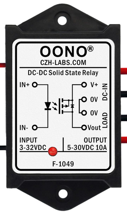
The F-1049 DC to DC Solid State Relay (SSR), manufactured by CZH-LABS (Part ID: OONO F-1049), is an electronic switching device designed to control high-voltage DC loads using a low-voltage DC control signal. Unlike traditional mechanical relays, the F-1049 SSR provides electrical isolation between the control and load circuits, ensuring safe operation and eliminating mechanical wear. This makes it ideal for applications requiring high reliability and fast switching.
Explore Projects Built with F-1049 DC to DC SSR


Explore Projects Built with F-1049 DC to DC SSR
Common Applications and Use Cases
- Industrial automation systems
- Motor control and DC load switching
- Battery management systems
- Renewable energy systems (e.g., solar inverters)
- Robotics and IoT devices
- High-speed switching applications
Technical Specifications
Key Technical Details
| Parameter | Value |
|---|---|
| Control Voltage (Input) | 3.0V to 32.0V DC |
| Load Voltage (Output) | 5.0V to 200.0V DC |
| Load Current (Max) | 10A |
| Isolation Voltage | 2500V AC |
| On-State Voltage Drop | ≤ 1.5V |
| Switching Speed | Turn-on: ≤ 10ms, Turn-off: ≤ 10ms |
| Operating Temperature | -30°C to +80°C |
| Dimensions | 58mm x 45mm x 25mm |
| Weight | 50g |
Pin Configuration and Descriptions
The F-1049 SSR has four terminals, as described in the table below:
| Pin Number | Label | Description |
|---|---|---|
| 1 | Control (+) | Positive terminal for the DC control signal (input voltage: 3.0V to 32.0V). |
| 2 | Control (-) | Negative terminal for the DC control signal (ground). |
| 3 | Load (+) | Positive terminal for the DC load circuit (output voltage: 5.0V to 200.0V). |
| 4 | Load (-) | Negative terminal for the DC load circuit (ground). |
Usage Instructions
How to Use the F-1049 SSR in a Circuit
Connect the Control Circuit:
- Attach the positive control signal to the
Control (+)terminal (Pin 1). - Connect the ground of the control signal to the
Control (-)terminal (Pin 2). - Ensure the control voltage is within the range of 3.0V to 32.0V DC.
- Attach the positive control signal to the
Connect the Load Circuit:
- Connect the positive side of the load to the
Load (+)terminal (Pin 3). - Connect the negative side of the load to the
Load (-)terminal (Pin 4). - Ensure the load voltage and current do not exceed 200V DC and 10A, respectively.
- Connect the positive side of the load to the
Power On:
- Apply the control voltage to activate the relay. The load circuit will be energized when the control signal is applied.
Switching:
- The relay will switch on or off based on the presence or absence of the control signal. The switching speed is ≤ 10ms.
Important Considerations and Best Practices
- Heat Dissipation: Ensure proper ventilation or use a heatsink if the relay operates near its maximum current rating.
- Isolation: Verify that the control and load circuits are electrically isolated to prevent damage.
- Polarity: Observe correct polarity for both control and load connections to avoid malfunction.
- Overvoltage Protection: Use appropriate protection (e.g., TVS diodes) to safeguard the relay from voltage spikes.
- Testing: Test the relay with a low-power load before connecting it to high-power equipment.
Example: Connecting the F-1049 SSR to an Arduino UNO
The F-1049 SSR can be controlled using an Arduino UNO. Below is an example circuit and code to toggle a DC load using the relay.
Circuit Diagram
- Connect the Arduino's digital pin (e.g., Pin 9) to the
Control (+)terminal of the SSR. - Connect the Arduino's GND to the
Control (-)terminal of the SSR. - Connect the DC load to the
Load (+)andLoad (-)terminals of the SSR.
Arduino Code
// Example code to control the F-1049 SSR with an Arduino UNO
// This code toggles the relay on and off every 2 seconds.

#define RELAY_PIN 9  // Define the Arduino pin connected to the SSR Control (+)

void setup() {
  pinMode(RELAY_PIN, OUTPUT);  // Set the relay pin as an output
}

void loop() {
  digitalWrite(RELAY_PIN, HIGH);  // Turn the relay ON
  delay(2000);                    // Wait for 2 seconds
  digitalWrite(RELAY_PIN, LOW);   // Turn the relay OFF
  delay(2000);                    // Wait for 2 seconds
}
Troubleshooting and FAQs
Common Issues and Solutions
| Issue | Possible Cause | Solution |
|---|---|---|
| Relay does not switch on | Insufficient control voltage | Ensure the control voltage is between 3.0V and 32.0V DC. |
| Load circuit does not energize | Incorrect load wiring or polarity | Verify the load connections and ensure correct polarity. |
| Excessive heat during operation | Overcurrent or poor ventilation | Reduce the load current or improve heat dissipation (e.g., add a heatsink). |
| Relay switches erratically | Electrical noise or unstable control signal | Use a decoupling capacitor on the control circuit to stabilize the signal. |
| No isolation between circuits | Faulty relay or incorrect wiring | Verify wiring and replace the relay if necessary. |
FAQs
Can the F-1049 SSR handle AC loads?
- No, the F-1049 is designed specifically for DC loads. For AC loads, use an AC-rated SSR.
What happens if the load exceeds 10A?
- Exceeding the maximum current rating can damage the relay. Use a relay with a higher current rating or reduce the load.
Is the relay suitable for PWM control?
- The F-1049 SSR is not optimized for high-frequency PWM control due to its switching speed (≤ 10ms). Use a MOSFET or similar device for high-speed switching.
Can I use the relay in outdoor environments?
- The relay is not weatherproof. Use an appropriate enclosure to protect it from moisture and dust.
By following this documentation, users can safely and effectively integrate the F-1049 DC to DC SSR into their projects.