
How to Use DIP Switch 8 Position: Examples, Pinouts, and Specs

 Design with DIP Switch 8 Position in Cirkit Designer
Introduction
The DIP Switch 8 Position is a compact, manually operated switch housed in a Dual In-line Package (DIP) format. It features 8 individual toggle switches, each of which can be set to either an ON or OFF position. This component is commonly used for configuring settings, selecting modes, or enabling/disabling features in electronic circuits without requiring software changes.
Explore Projects Built with DIP Switch 8 Position
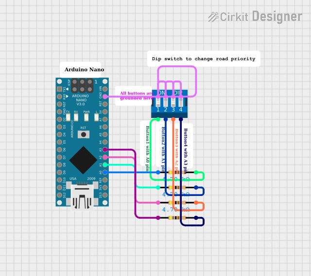 Open Project in Cirkit Designer
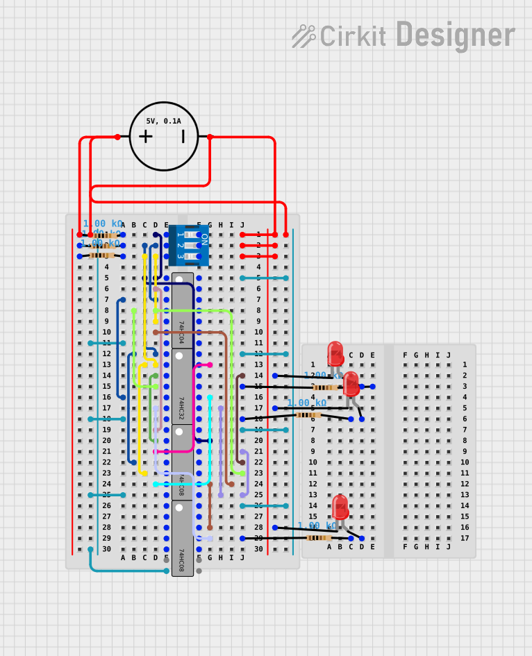 Open Project in Cirkit Designer
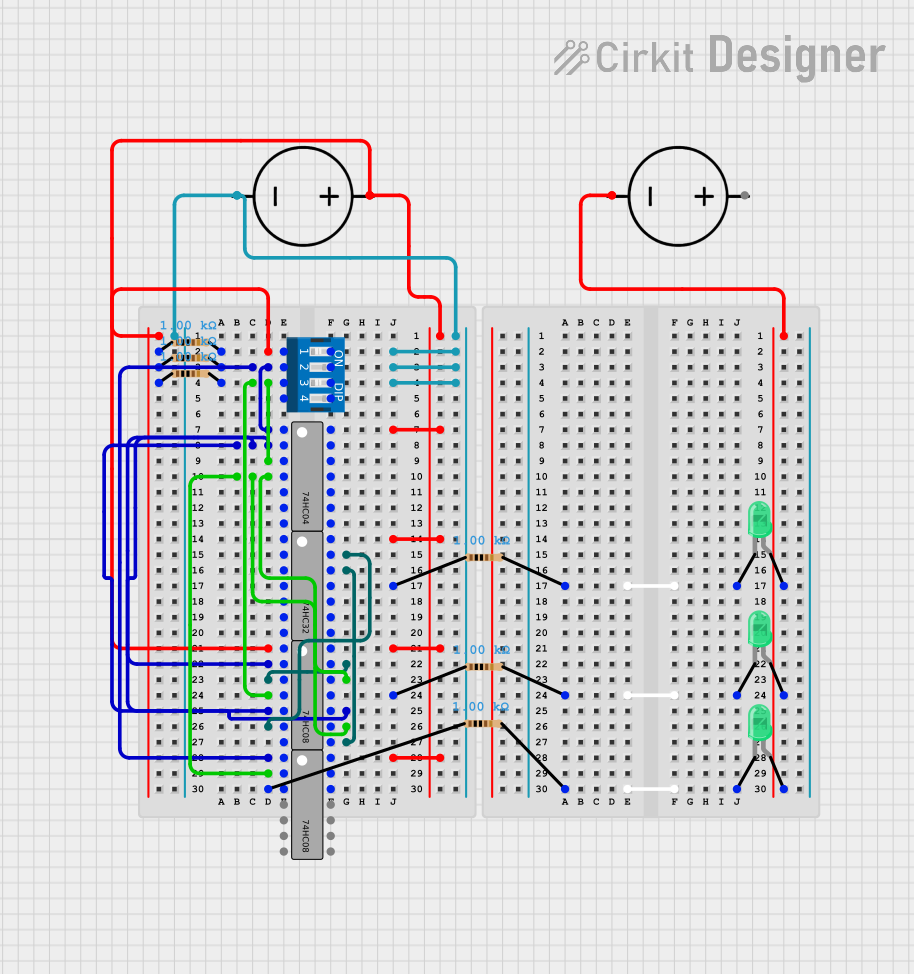 Open Project in Cirkit Designer
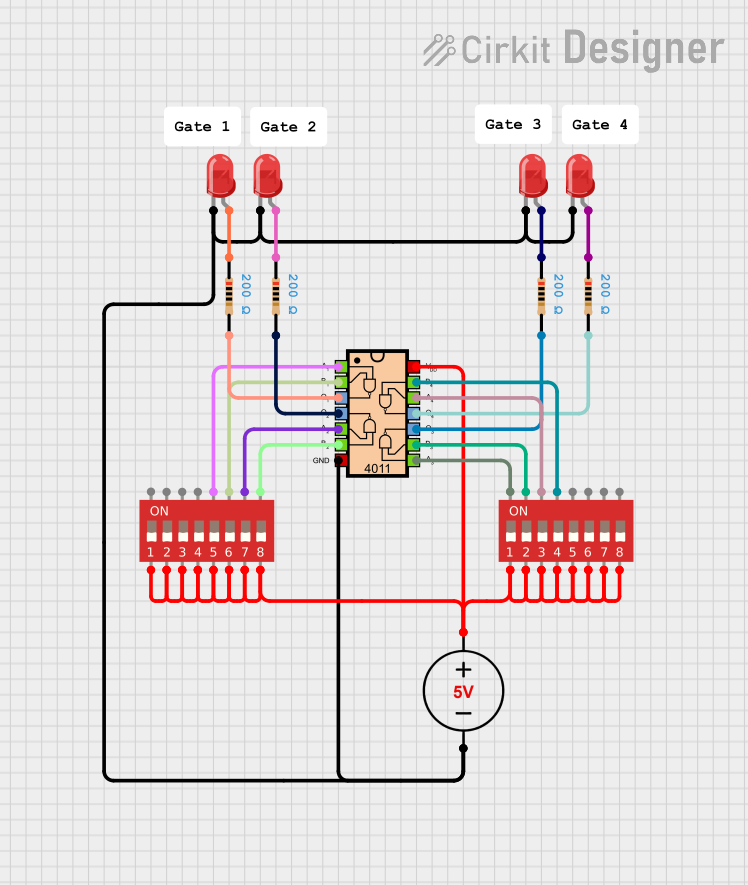 Open Project in Cirkit Designer
Explore Projects Built with DIP Switch 8 Position
Open Project in Cirkit DesignerOpen Project in Cirkit DesignerOpen Project in Cirkit DesignerOpen Project in Cirkit DesignerCommon Applications
- Configuring microcontroller or hardware settings
- Setting device addresses in communication protocols (e.g., I2C, RS-485)
- Enabling or disabling features in embedded systems
- Debugging and testing circuits
- User-selectable options in consumer electronics
Technical Specifications
The following table outlines the key technical details of the DIP Switch 8 Position:
| Parameter | Value |
|---|---|
| Number of Positions | 8 |
| Switch Type | SPST (Single Pole Single Throw) |
| Contact Rating | 25 mA at 24 VDC |
| Insulation Resistance | ≥ 100 MΩ at 500 VDC |
| Contact Resistance | ≤ 50 mΩ |
| Operating Temperature | -40°C to +85°C |
| Actuator Type | Slide |
| Mounting Type | Through-hole |
| Dimensions | ~10 mm x 25 mm x 5 mm |
Pin Configuration and Descriptions
The DIP Switch 8 Position has 16 pins in total, with each switch having two pins. The following table describes the pin configuration:
| Pin Number | Description |
|---|---|
| 1, 2 | Switch 1 terminals |
| 3, 4 | Switch 2 terminals |
| 5, 6 | Switch 3 terminals |
| 7, 8 | Switch 4 terminals |
| 9, 10 | Switch 5 terminals |
| 11, 12 | Switch 6 terminals |
| 13, 14 | Switch 7 terminals |
| 15, 16 | Switch 8 terminals |
Each pair of pins corresponds to one switch. When the switch is in the ON position, the two pins are electrically connected. When in the OFF position, the pins are disconnected.
Usage Instructions
How to Use the DIP Switch in a Circuit
- Mounting the DIP Switch: Solder the DIP switch onto a PCB using the through-hole pins. Ensure proper alignment with the circuit design.
- Connecting to a Circuit: Connect one terminal of each switch to the desired input or output line. The other terminal can be connected to ground, power, or another circuit node, depending on the application.
- Configuring the Switches: Slide each switch to the ON or OFF position to configure the desired settings. Use a small tool (e.g., a screwdriver) if necessary to avoid damaging the actuator.
Important Considerations
- Debouncing: Mechanical switches, including DIP switches, may produce noise or "bouncing" when toggled. Use a debouncing circuit or software algorithm to ensure stable readings.
- Voltage and Current Ratings: Do not exceed the specified voltage and current ratings to avoid damaging the switch.
- Accessibility: Place the DIP switch in an accessible location on the PCB for easy configuration.
- Labeling: Clearly label the switches on the PCB to indicate their function or purpose.
Example: Using a DIP Switch with Arduino UNO
The following example demonstrates how to read the state of an 8-position DIP switch using an Arduino UNO. Each switch is connected to a digital input pin with pull-down resistors.
Circuit Connections
- Connect one terminal of each switch to digital pins 2 through 9 on the Arduino.
- Connect the other terminal of each switch to ground.
- Use pull-down resistors (10 kΩ) between each digital pin and ground to ensure stable readings.
Arduino Code
// DIP Switch 8 Position Example with Arduino UNO
// Reads the state of each switch and prints the results to the Serial Monitor.

const int switchPins[8] = {2, 3, 4, 5, 6, 7, 8, 9}; // Digital pins for switches
int switchStates[8]; // Array to store switch states

void setup() {
  Serial.begin(9600); // Initialize serial communication
  for (int i = 0; i < 8; i++) {
    pinMode(switchPins[i], INPUT); // Set each pin as input
  }
}

void loop() {
  for (int i = 0; i < 8; i++) {
    switchStates[i] = digitalRead(switchPins[i]); // Read each switch state
  }

  // Print switch states to Serial Monitor
  Serial.print("Switch States: ");
  for (int i = 0; i < 8; i++) {
    Serial.print(switchStates[i]);
    Serial.print(" ");
  }
  Serial.println(); // New line for readability
  delay(500); // Delay for stability
}
Troubleshooting and FAQs
Common Issues
Switch Not Responding
- Cause: Poor soldering or loose connections.
- Solution: Inspect and re-solder the connections. Ensure the switch is properly mounted.
Incorrect Readings
- Cause: Lack of pull-down resistors or switch bouncing.
- Solution: Add pull-down resistors to each input pin. Use software debouncing if necessary.
Switch Feels Stiff or Hard to Toggle
- Cause: Dust or debris in the switch mechanism.
- Solution: Clean the switch gently with compressed air. Avoid using excessive force.
FAQs
Q: Can I use the DIP switch for high-current applications?
A: No, the DIP switch is designed for low-current applications (up to 25 mA). For high-current circuits, use relays or other suitable components.
Q: How do I debounce a DIP switch in software?
A: Implement a delay (e.g., 10-50 ms) after reading the switch state to filter out noise. Alternatively, use a debouncing library if available.
Q: Can I use fewer than 8 switches in my circuit?
A: Yes, you can use as many switches as needed. Leave unused switches in the OFF position or disconnect them from the circuit.
This concludes the documentation for the DIP Switch 8 Position.