How to Use LCD1602 RGB: Examples, Pinouts, and Specs
Introduction
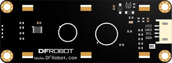
The LCD1602 RGB by DFRobot (Part ID: LCD1602) is a 16x2 character LCD display featuring RGB backlighting. This versatile display allows users to customize the backlight color, making it suitable for a wide range of applications. It is designed for easy integration with microcontrollers, such as Arduino, and is ideal for displaying text, numbers, and simple symbols.
Explore Projects Built with LCD1602 RGB
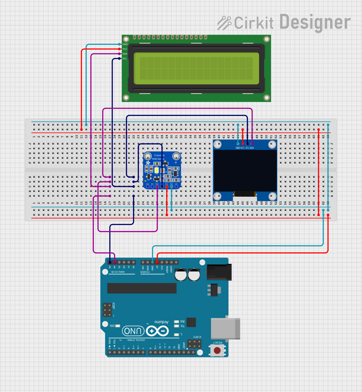

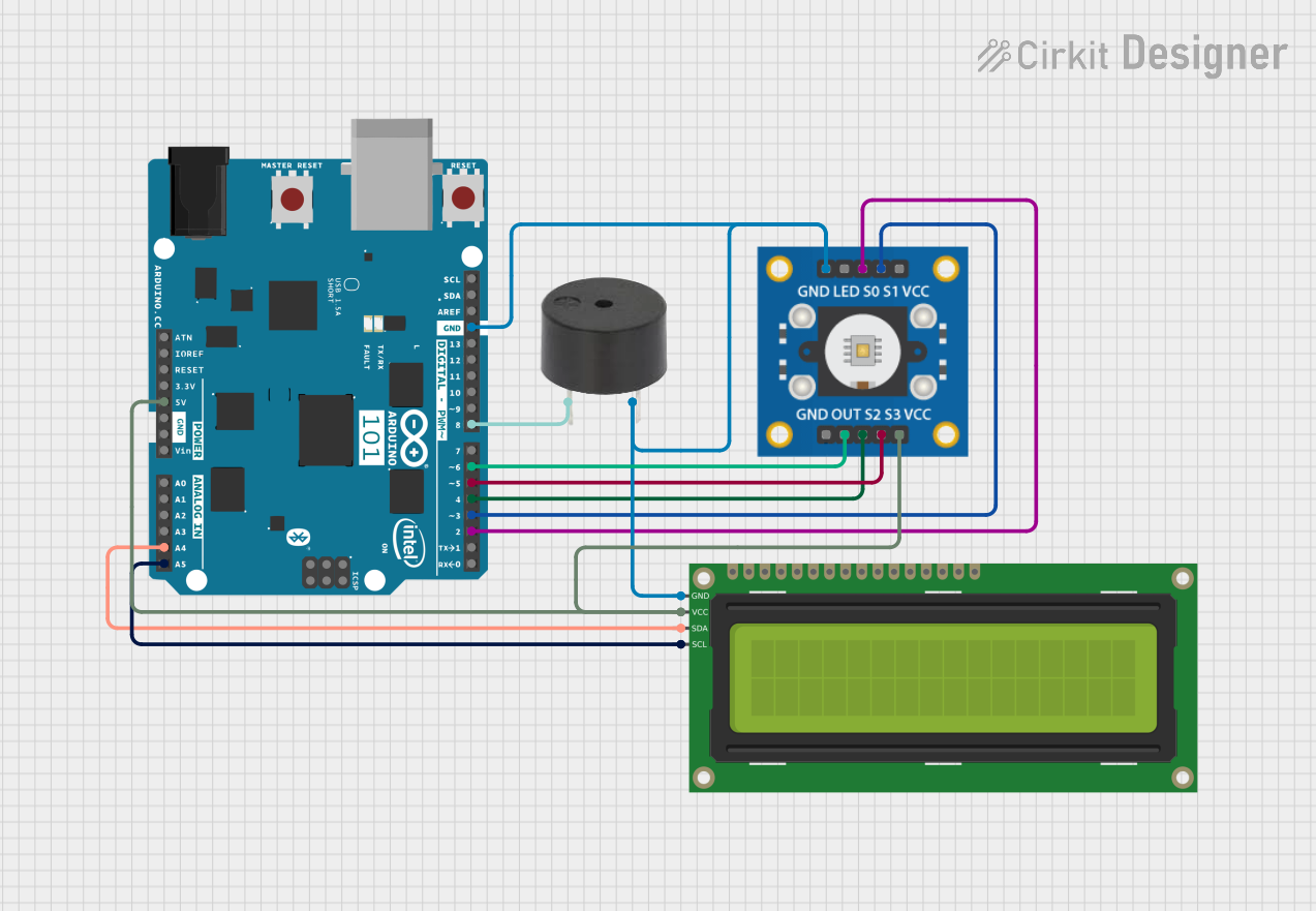
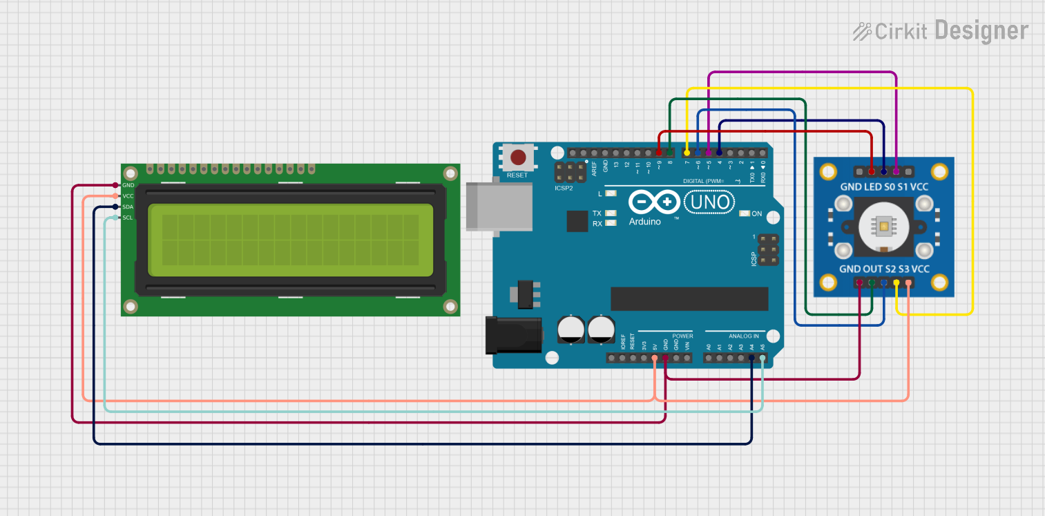
Explore Projects Built with LCD1602 RGB
Common Applications and Use Cases
- DIY Electronics Projects: Displaying sensor data, system status, or user instructions.
- Embedded Systems: Providing a user interface for microcontroller-based systems.
- Educational Projects: Teaching basic electronics and programming concepts.
- Prototyping: Rapid development of user interfaces for prototypes.
Technical Specifications
The following table outlines the key technical details of the LCD1602 RGB:
| Parameter | Value |
|---|---|
| Display Type | 16x2 Character LCD |
| Backlight | RGB (customizable colors) |
| Operating Voltage | 5V DC |
| Operating Current | 60mA (typical) |
| Communication Interface | I2C |
| I2C Address (default) | 0x27 |
| Dimensions | 80mm x 36mm x 12mm |
| Operating Temperature | -20°C to 70°C |
Pin Configuration and Descriptions
The LCD1602 RGB uses an I2C interface, which simplifies wiring. Below is the pin configuration:
| Pin | Name | Description |
|---|---|---|
| 1 | GND | Ground connection |
| 2 | VCC | Power supply (5V DC) |
| 3 | SDA | I2C data line |
| 4 | SCL | I2C clock line |
Usage Instructions
Connecting the LCD1602 RGB to an Arduino UNO
To use the LCD1602 RGB with an Arduino UNO, follow these steps:
Wiring:
- Connect the GND pin of the LCD to the GND pin on the Arduino.
- Connect the VCC pin of the LCD to the 5V pin on the Arduino.
- Connect the SDA pin of the LCD to the A4 pin on the Arduino.
- Connect the SCL pin of the LCD to the A5 pin on the Arduino.
Install Required Libraries:
- Download and install the
LiquidCrystal_I2Clibrary from the Arduino Library Manager.
- Download and install the
Upload Example Code: Use the following example code to display text and change the backlight color:
#include <Wire.h>
#include <LiquidCrystal_I2C.h>

// Initialize the LCD with I2C address 0x27 and 16x2 dimensions
LiquidCrystal_I2C lcd(0x27, 16, 2);

void setup() {
  lcd.init(); // Initialize the LCD
  lcd.backlight(); // Turn on the backlight

  // Display a message on the LCD
  lcd.setCursor(0, 0); // Set cursor to the first row, first column
  lcd.print("Hello, World!");

  lcd.setCursor(0, 1); // Set cursor to the second row, first column
  lcd.print("RGB Backlight!");
}

void loop() {
  // Example: Change backlight color (if supported by the library)
  // Note: Some libraries may not support RGB control directly.
  // Check the library documentation for RGB control functions.
}
Important Considerations and Best Practices
- Power Supply: Ensure a stable 5V power supply to avoid flickering or malfunction.
- I2C Address: The default I2C address is
0x27. If the display does not respond, use an I2C scanner sketch to confirm the address. - Library Compatibility: Use a compatible library like
LiquidCrystal_I2Cto simplify programming. - Backlight Control: Some libraries may not support RGB backlight control directly. Refer to the library documentation for advanced features.
Troubleshooting and FAQs
Common Issues and Solutions
No Display Output:
- Cause: Incorrect wiring or power supply.
- Solution: Double-check all connections and ensure the power supply is 5V.
Flickering or Dim Backlight:
- Cause: Insufficient current supply.
- Solution: Use a stable power source capable of providing at least 60mA.
I2C Communication Failure:
- Cause: Incorrect I2C address or wiring.
- Solution: Use an I2C scanner sketch to detect the correct address and verify SDA/SCL connections.
Backlight Color Not Changing:
- Cause: Library limitations or unsupported feature.
- Solution: Check the library documentation for RGB control functions or use a different library.
FAQs
Q1: Can I use the LCD1602 RGB with a 3.3V microcontroller?
A1: The LCD1602 RGB is designed for 5V operation. Use a level shifter to safely interface with 3.3V microcontrollers.
Q2: How do I adjust the contrast of the display?
A2: The contrast is typically pre-set. If adjustable, a potentiometer or software control may be required.
Q3: Can I display custom characters?
A3: Yes, the LCD1602 supports custom characters. Refer to the LiquidCrystal_I2C library documentation for instructions.
Q4: What is the maximum cable length for I2C communication?
A4: For reliable communication, keep the cable length under 1 meter. Use shielded cables for longer distances.
This concludes the documentation for the LCD1602 RGB. For further assistance, refer to the DFRobot product page or community forums.