How to Use DC motor with Gear: Examples, Pinouts, and Specs
Introduction
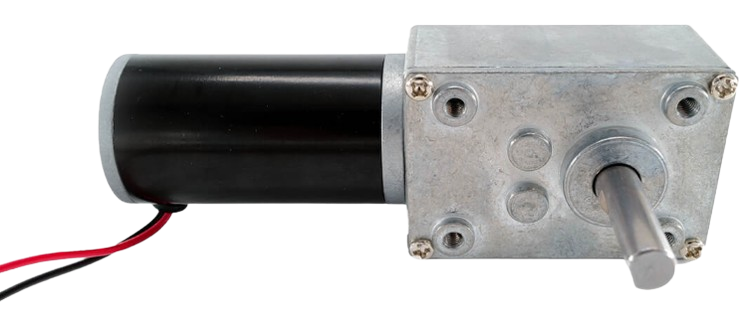
A DC motor with a gear system is an electromechanical device that converts electrical energy into mechanical energy. The integrated gear system reduces the motor's speed while increasing its torque, making it ideal for applications requiring precise control and high torque at low speeds. These motors are widely used in robotics, conveyor systems, electric vehicles, and automated machinery.
Explore Projects Built with DC motor with Gear

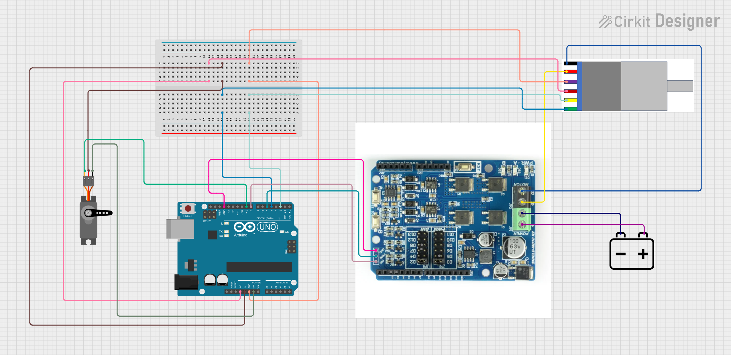
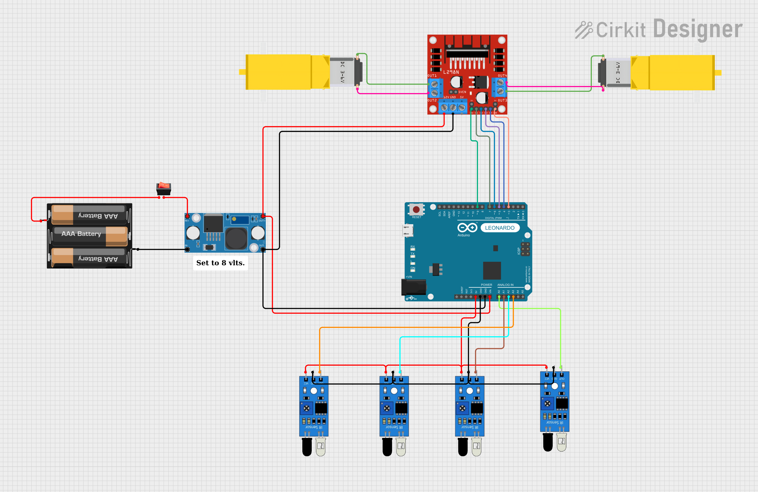
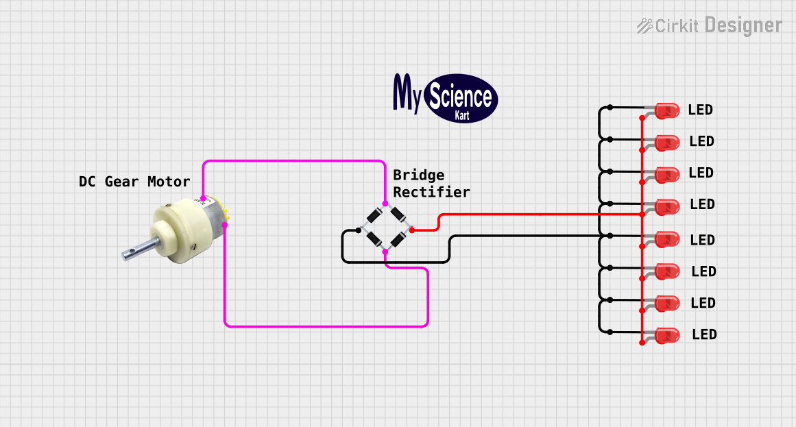
Explore Projects Built with DC motor with Gear
Common Applications:
- Robotics (e.g., robotic arms, mobile robots)
- Conveyor belts and material handling systems
- Electric vehicles and motorized toys
- Automated door systems
- Precision control mechanisms in industrial equipment
Technical Specifications
Key Technical Details:
- Operating Voltage: 6V to 24V (varies by model)
- Current Rating: 100mA to 2A (depending on load and motor size)
- Gear Ratio: Common ratios include 10:1, 30:1, 50:1, and higher
- Output Shaft Speed: 10 RPM to 500 RPM (depending on gear ratio)
- Torque: Up to 10 Nm (varies by model)
- Motor Type: Brushed DC motor
- Shaft Diameter: Typically 4mm to 6mm
- Mounting Holes: Standard M3 or M4 screw holes
Pin Configuration and Descriptions:
| Pin/Terminal | Description |
|---|---|
| Terminal 1 | Positive terminal for DC power input |
| Terminal 2 | Negative terminal for DC power input |
Note: Some DC motors with gears may include additional terminals for encoders or feedback systems. Refer to the specific motor datasheet for details.
Usage Instructions
How to Use the Component in a Circuit:
Power Supply:
- Connect the motor terminals to a DC power source within the specified voltage range.
- Use a motor driver or H-bridge circuit (e.g., L298N or L293D) to control the motor's speed and direction.
Direction Control:
- Reverse the polarity of the power supply to change the motor's rotation direction.
- For precise control, use a microcontroller (e.g., Arduino UNO) with a motor driver.
Speed Control:
- Use Pulse Width Modulation (PWM) to control the motor's speed.
- Most motor drivers support PWM signals from microcontrollers.
Mounting:
- Secure the motor using the provided mounting holes.
- Ensure proper alignment to avoid stress on the motor shaft.
Important Considerations:
- Current Limiting: Use a current-limiting resistor or motor driver to prevent overloading the motor.
- Heat Dissipation: Prolonged operation at high torque may cause the motor to heat up. Ensure proper ventilation or heat sinking.
- Power Supply: Use a stable DC power source to avoid voltage fluctuations that could damage the motor.
- Gearbox Maintenance: Periodically check the gearbox for wear and apply lubrication if necessary.
Example: Controlling a DC Motor with Gear Using Arduino UNO
Below is an example of how to control a DC motor with a gear system using an Arduino UNO and an L298N motor driver.
// Example: Controlling a DC motor with gear using Arduino UNO
// Connect the motor to the L298N motor driver and the driver to the Arduino

// Define motor control pins
const int motorPin1 = 9; // IN1 on L298N
const int motorPin2 = 10; // IN2 on L298N
const int enablePin = 11; // ENA on L298N (for speed control)

void setup() {
  // Set motor control pins as outputs
  pinMode(motorPin1, OUTPUT);
  pinMode(motorPin2, OUTPUT);
  pinMode(enablePin, OUTPUT);
}

void loop() {
  // Rotate motor in one direction
  digitalWrite(motorPin1, HIGH); // Set IN1 high
  digitalWrite(motorPin2, LOW);  // Set IN2 low
  analogWrite(enablePin, 150);   // Set speed (0-255)

  delay(2000); // Run for 2 seconds

  // Stop the motor
  digitalWrite(motorPin1, LOW);
  digitalWrite(motorPin2, LOW);
  delay(1000); // Pause for 1 second

  // Rotate motor in the opposite direction
  digitalWrite(motorPin1, LOW);  // Set IN1 low
  digitalWrite(motorPin2, HIGH); // Set IN2 high
  analogWrite(enablePin, 200);   // Set speed (0-255)

  delay(2000); // Run for 2 seconds

  // Stop the motor
  digitalWrite(motorPin1, LOW);
  digitalWrite(motorPin2, LOW);
  delay(1000); // Pause for 1 second
}
Troubleshooting and FAQs
Common Issues:
Motor Not Spinning:
- Cause: Insufficient power supply or loose connections.
- Solution: Check the power supply voltage and ensure all connections are secure.
Motor Overheating:
- Cause: Prolonged operation at high torque or insufficient ventilation.
- Solution: Reduce the load on the motor or improve heat dissipation.
Noisy Operation:
- Cause: Worn-out gears or lack of lubrication.
- Solution: Inspect the gearbox and apply appropriate lubrication.
Inconsistent Speed:
- Cause: Voltage fluctuations or poor PWM signal quality.
- Solution: Use a stable power source and ensure proper PWM signal generation.
FAQs:
Q: Can I run the motor directly from an Arduino pin?
A: No, the Arduino pins cannot supply enough current. Use a motor driver or external power source.Q: How do I select the right gear ratio?
A: Choose a gear ratio based on the required torque and speed for your application. Higher ratios provide more torque but reduce speed.Q: Can I use this motor with a battery?
A: Yes, ensure the battery voltage matches the motor's operating range and can supply sufficient current.Q: How do I reverse the motor's direction?
A: Swap the polarity of the power supply or use a motor driver to control the direction programmatically.
This documentation provides a comprehensive guide to understanding, using, and troubleshooting a DC motor with a gear system.