
How to Use MAX98357A: Examples, Pinouts, and Specs
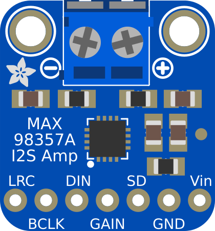
 Design with MAX98357A in Cirkit Designer
Introduction
The MAX98357A is a digital audio amplifier designed to deliver high-quality audio output with minimal distortion. It integrates a built-in digital-to-analog converter (DAC) and supports I2S (Inter-IC Sound) audio input, simplifying the design of audio systems. This component is widely used in portable devices, smart speakers, and other audio applications where compact size and efficient performance are critical.
Explore Projects Built with MAX98357A
 Open Project in Cirkit Designer
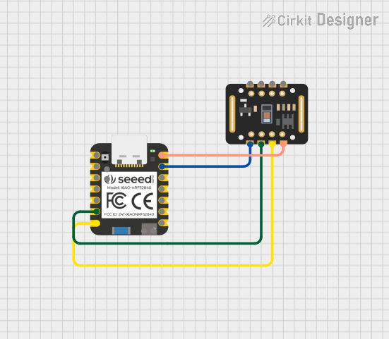 Open Project in Cirkit Designer
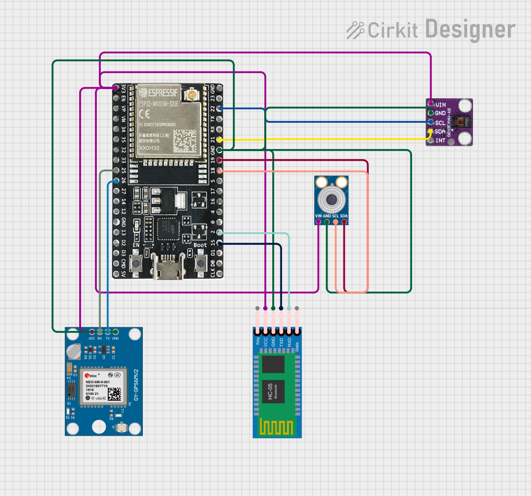 Open Project in Cirkit Designer
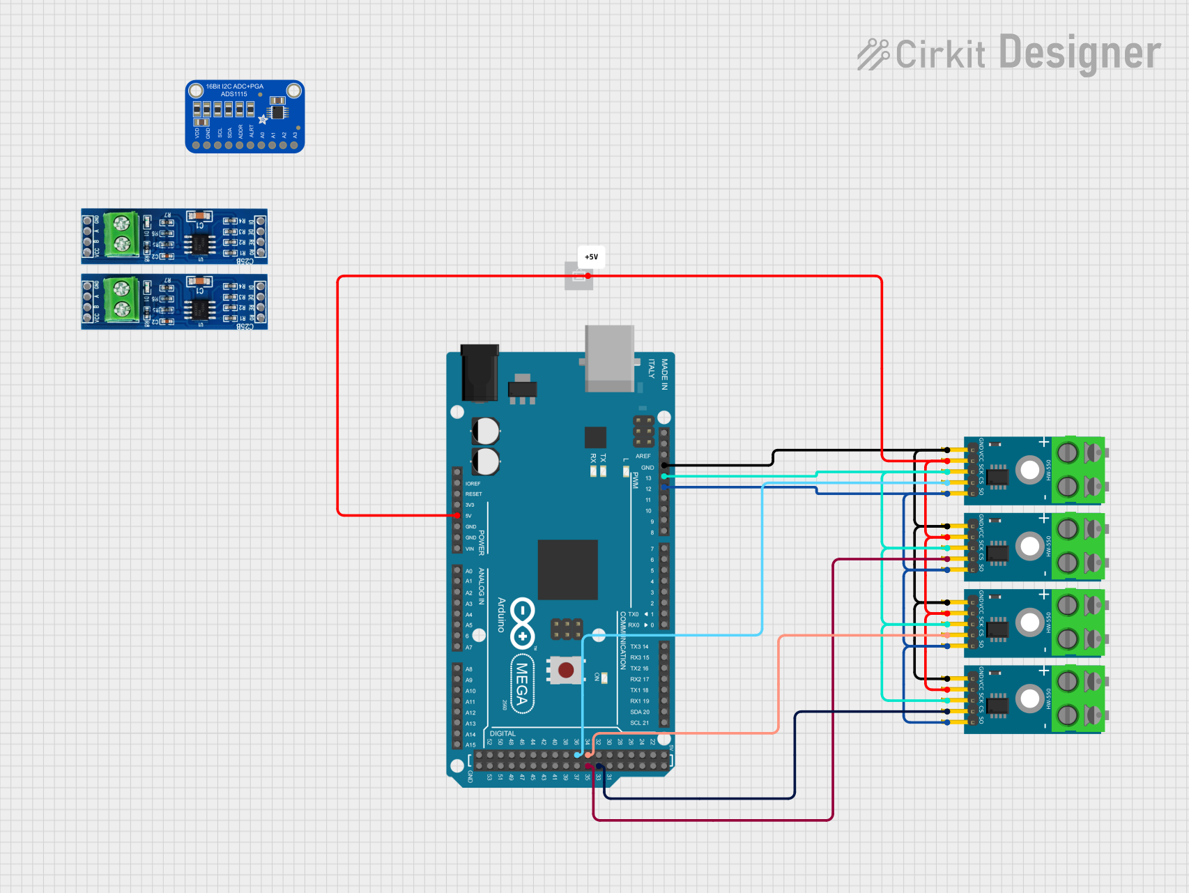 Open Project in Cirkit Designer
Explore Projects Built with MAX98357A
Open Project in Cirkit DesignerOpen Project in Cirkit DesignerOpen Project in Cirkit DesignerOpen Project in Cirkit DesignerCommon Applications:
- Portable audio devices
- Smart speakers and voice assistants
- IoT devices with audio output
- Home audio systems
- Embedded systems requiring high-quality sound
Technical Specifications
Below are the key technical details of the MAX98357A:
| Parameter | Value |
|---|---|
| Supply Voltage (VDD) | 2.5V to 5.5V |
| Output Power | 3.2W at 4Ω load, 10% THD+N |
| Input Format | I2S (Inter-IC Sound) |
| Signal-to-Noise Ratio (SNR) | 98 dB |
| Total Harmonic Distortion | 0.013% (1kHz, 8Ω load, 1W output) |
| Efficiency | 92% (at 1.8W, 8Ω load) |
| Shutdown Current | 0.5 µA |
| Operating Temperature | -40°C to +85°C |
Pin Configuration and Descriptions
The MAX98357A is available in a compact 9-pin WLP (Wafer-Level Package). Below is the pinout and description:
| Pin Name | Pin Number | Description |
|---|---|---|
| GND | 1 | Ground connection |
| VDD | 2 | Power supply input (2.5V to 5.5V) |
| OUT+ | 3 | Positive speaker output |
| OUT- | 4 | Negative speaker output |
| SD_MODE | 5 | Shutdown and mode selection pin |
| DIN | 6 | I2S data input |
| BCLK | 7 | I2S bit clock input |
| LRCLK | 8 | I2S left-right clock input |
| GAIN | 9 | Gain selection pin (sets output gain level) |
Usage Instructions
How to Use the MAX98357A in a Circuit
- Power Supply: Connect the VDD pin to a stable power source within the range of 2.5V to 5.5V. Ensure proper decoupling with a capacitor (e.g., 10 µF) close to the VDD pin.
- Speaker Connection: Connect the OUT+ and OUT- pins to the speaker terminals. The MAX98357A supports differential output, so no external filter is required.
- I2S Input: Connect the I2S signals (DIN, BCLK, and LRCLK) from your audio source (e.g., microcontroller or audio processor) to the corresponding pins on the MAX98357A.
- Mode Selection: Use the SD_MODE pin to enable or disable the amplifier and configure its mode. Refer to the datasheet for specific mode settings.
- Gain Configuration: Set the desired output gain using the GAIN pin. This can be done by connecting the pin to GND, VDD, or leaving it floating, depending on the required gain level.
Important Considerations and Best Practices
- Thermal Management: Ensure proper heat dissipation, especially when driving high-power loads.
- Decoupling Capacitors: Place decoupling capacitors close to the VDD pin to minimize noise and ensure stable operation.
- I2S Configuration: Verify that the I2S settings (e.g., bit depth, sample rate) of the audio source match the MAX98357A's supported formats.
- Speaker Impedance: Use speakers with an impedance of 4Ω or higher for optimal performance.
Example: Connecting MAX98357A to an Arduino UNO
The MAX98357A can be easily interfaced with an Arduino UNO for audio playback. Below is an example of how to connect and program the MAX98357A:
Wiring Diagram:
| MAX98357A Pin | Arduino UNO Pin |
|---|---|
| VDD | 5V |
| GND | GND |
| DIN | Pin 11 (MOSI) |
| BCLK | Pin 13 (SCK) |
| LRCLK | Pin 10 |
| SD_MODE | 3.3V or GND |
| OUT+ | Speaker + |
| OUT- | Speaker - |
Arduino Code:
#include <I2S.h> // Include the I2S library for audio communication

void setup() {
  // Initialize I2S for audio output
  if (!I2S.begin(I2S_PHILIPS_MODE, 44100, 16)) {
    // Check if I2S initialization failed
    while (1) {
      // Stay in this loop if initialization fails
    }
  }
}

void loop() {
  // Generate a simple sine wave for testing
  for (int i = 0; i < 360; i++) {
    // Calculate the sine wave value
    int sample = 32767 * sin(i * PI / 180);
    // Write the sample to the I2S output
    I2S.write(sample);
  }
}
Note: The above code generates a simple sine wave for testing purposes. Replace it with actual audio data for real applications.
Troubleshooting and FAQs
Common Issues and Solutions
No Audio Output:
- Verify that the I2S signals (DIN, BCLK, LRCLK) are correctly connected and configured.
- Check the power supply voltage and ensure it is within the specified range.
- Ensure the SD_MODE pin is not in shutdown mode.
Distorted Audio:
- Confirm that the speaker impedance matches the recommended value (4Ω or higher).
- Check for noise or instability in the power supply.
- Verify that the I2S audio source is configured with the correct bit depth and sample rate.
Overheating:
- Ensure proper ventilation and heat dissipation for the MAX98357A.
- Avoid driving the amplifier at maximum power for extended periods without adequate cooling.
FAQs
Q: Can the MAX98357A drive stereo speakers?
A: No, the MAX98357A is a mono amplifier. For stereo output, you will need two MAX98357A modules.
Q: What is the maximum sample rate supported by the MAX98357A?
A: The MAX98357A supports sample rates up to 96 kHz.
Q: Does the MAX98357A require an external DAC?
A: No, the MAX98357A has a built-in DAC, so no external DAC is needed.
Q: Can I use the MAX98357A with a 3.3V microcontroller?
A: Yes, the MAX98357A is compatible with 3.3V logic levels for I2S signals.