How to Use DC-DC buck converter: Examples, Pinouts, and Specs
Introduction
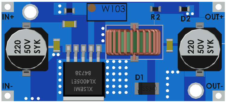
The XL4015 is a high-efficiency DC-DC buck converter manufactured by XLSEMI. It is designed to step down a higher input voltage to a lower output voltage while maintaining high efficiency, making it ideal for applications requiring regulated power delivery. The XL4015 is widely used in power supply circuits, battery chargers, LED drivers, and other electronic systems where efficient voltage regulation is critical.
Explore Projects Built with DC-DC buck converter


Explore Projects Built with DC-DC buck converter
Common Applications
- Power supply for microcontrollers and embedded systems
- Battery charging circuits
- LED lighting systems
- Voltage regulation in industrial and automotive electronics
- DIY electronics projects
Technical Specifications
The XL4015 DC-DC buck converter offers robust performance and flexibility. Below are its key technical specifications:
| Parameter | Value |
|---|---|
| Input Voltage Range | 4.0V to 38.0V |
| Output Voltage Range | 1.25V to 36.0V (adjustable) |
| Maximum Output Current | 5A (with proper heat dissipation) |
| Switching Frequency | 180 kHz |
| Efficiency | Up to 96% |
| Output Ripple | ≤ 30mV |
| Operating Temperature | -40°C to +85°C |
| Dimensions | 51mm x 26mm x 14mm |
Pin Configuration and Descriptions
The XL4015 module typically has the following pin configuration:
| Pin Name | Description |
|---|---|
| VIN | Input voltage pin. Connect the higher input voltage (4.0V to 38.0V). |
| VOUT | Output voltage pin. Provides the regulated lower output voltage (1.25V to 36V). |
| GND | Ground pin. Common ground for input and output. |
| ADJ | Voltage adjustment pin. Use a potentiometer to set the desired output voltage. |
Usage Instructions
How to Use the XL4015 in a Circuit
Connect the Input Voltage:
- Connect the positive terminal of the input voltage source to the
VINpin. - Connect the negative terminal of the input voltage source to the
GNDpin.
- Connect the positive terminal of the input voltage source to the
Set the Output Voltage:
- Use the onboard potentiometer to adjust the output voltage.
- Turn the potentiometer clockwise to increase the output voltage and counterclockwise to decrease it.
- Use a multimeter to measure the output voltage at the
VOUTpin while adjusting.
Connect the Load:
- Connect the positive terminal of the load to the
VOUTpin. - Connect the negative terminal of the load to the
GNDpin.
- Connect the positive terminal of the load to the
Ensure Proper Heat Dissipation:
- For currents above 3A, attach a heatsink to the XL4015 module to prevent overheating.
Important Considerations
- Input Voltage: Ensure the input voltage is at least 1.5V higher than the desired output voltage.
- Current Limitation: Do not exceed the maximum output current of 5A. Use proper cooling for high-current applications.
- Output Ripple: Add a capacitor (e.g., 100µF) across the output terminals to reduce voltage ripple if needed.
- Polarity: Double-check the polarity of the input and output connections to avoid damage.
Example: Using XL4015 with Arduino UNO
The XL4015 can be used to power an Arduino UNO by stepping down a 12V input to 5V. Below is an example circuit and code:
Circuit Connections
- Connect a 12V DC power supply to the
VINandGNDpins of the XL4015. - Adjust the potentiometer to set the output voltage to 5V.
- Connect the
VOUTpin of the XL4015 to the5Vpin of the Arduino UNO. - Connect the
GNDpin of the XL4015 to theGNDpin of the Arduino UNO.
Arduino Code Example
// Example code to blink an LED using Arduino UNO powered by XL4015
// Ensure the XL4015 output is set to 5V before connecting to Arduino

const int ledPin = 13; // Built-in LED pin on Arduino UNO

void setup() {
  pinMode(ledPin, OUTPUT); // Set LED pin as output
}

void loop() {
  digitalWrite(ledPin, HIGH); // Turn the LED on
  delay(1000);                // Wait for 1 second
  digitalWrite(ledPin, LOW);  // Turn the LED off
  delay(1000);                // Wait for 1 second
}
Troubleshooting and FAQs
Common Issues and Solutions
No Output Voltage:
- Cause: Incorrect input connections or insufficient input voltage.
- Solution: Verify the input voltage is within the specified range and check the polarity.
Output Voltage Not Adjustable:
- Cause: Faulty potentiometer or incorrect adjustment.
- Solution: Replace the potentiometer or ensure proper adjustment using a multimeter.
Overheating:
- Cause: High current draw without adequate cooling.
- Solution: Attach a heatsink or reduce the load current.
High Output Ripple:
- Cause: Insufficient filtering.
- Solution: Add a capacitor (e.g., 100µF or higher) across the output terminals.
FAQs
Q: Can the XL4015 be used to charge batteries?
- A: Yes, the XL4015 can be used for battery charging. Ensure the output voltage and current are set according to the battery specifications.
Q: What is the maximum input voltage for the XL4015?
- A: The maximum input voltage is 38V. Exceeding this may damage the module.
Q: How do I reduce noise in the output voltage?
- A: Use additional capacitors across the output terminals and ensure proper grounding.
Q: Can the XL4015 be used with a solar panel?
- A: Yes, the XL4015 can regulate the output voltage from a solar panel, provided the input voltage is within the specified range.
This concludes the documentation for the XL4015 DC-DC buck converter.