How to Use Adafruit LM3671 Buck Converter: Examples, Pinouts, and Specs
Introduction
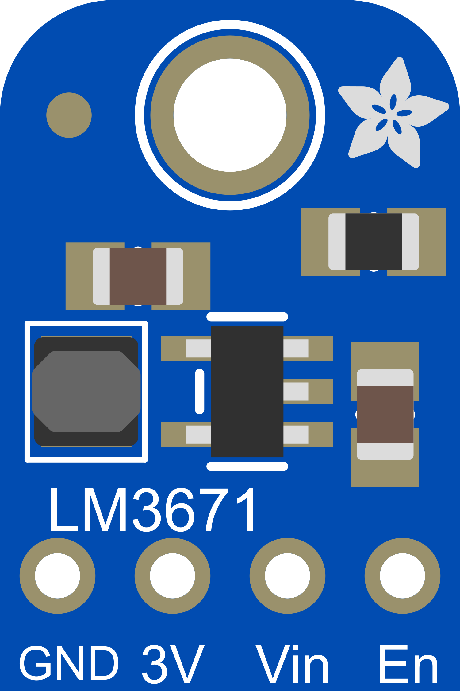
The Adafruit LM3671 Buck Converter is a compact, high-efficiency power module designed to step down higher voltage inputs to a lower voltage output. This component is essential in applications where battery life is critical, and it is commonly used to power low-power electronics such as microcontrollers, sensors, and small motors. Its efficiency and small footprint make it ideal for portable devices, IoT applications, and embedded systems.
Explore Projects Built with Adafruit LM3671 Buck Converter


Explore Projects Built with Adafruit LM3671 Buck Converter
Technical Specifications
Key Technical Details
- Input Voltage Range: 2.0V to 5.5V
- Output Voltage: 3.3V (fixed output version)
- Maximum Output Current: 600mA
- Switching Frequency: 2MHz
- Efficiency: Up to 95%
- Operating Temperature Range: -30°C to +85°C
Pin Configuration and Descriptions
| Pin Number | Name | Description |
|---|---|---|
| 1 | VIN | Input voltage supply. Connect to a 2.0V to 5.5V power source. |
| 2 | GND | Ground reference for the circuit. |
| 3 | SW | Switch node. Connect to the inductor. |
| 4 | VOUT | Regulated output voltage. Provides a 3.3V output. |
| 5 | FB | Feedback pin. Internally connected for fixed output versions. |
| 6 | EN | Enable pin. Drive high to turn on the converter, low to turn it off. |
| 7 | PG | Power good output. Goes high when VOUT is within regulation. |
Usage Instructions
How to Use the Component in a Circuit
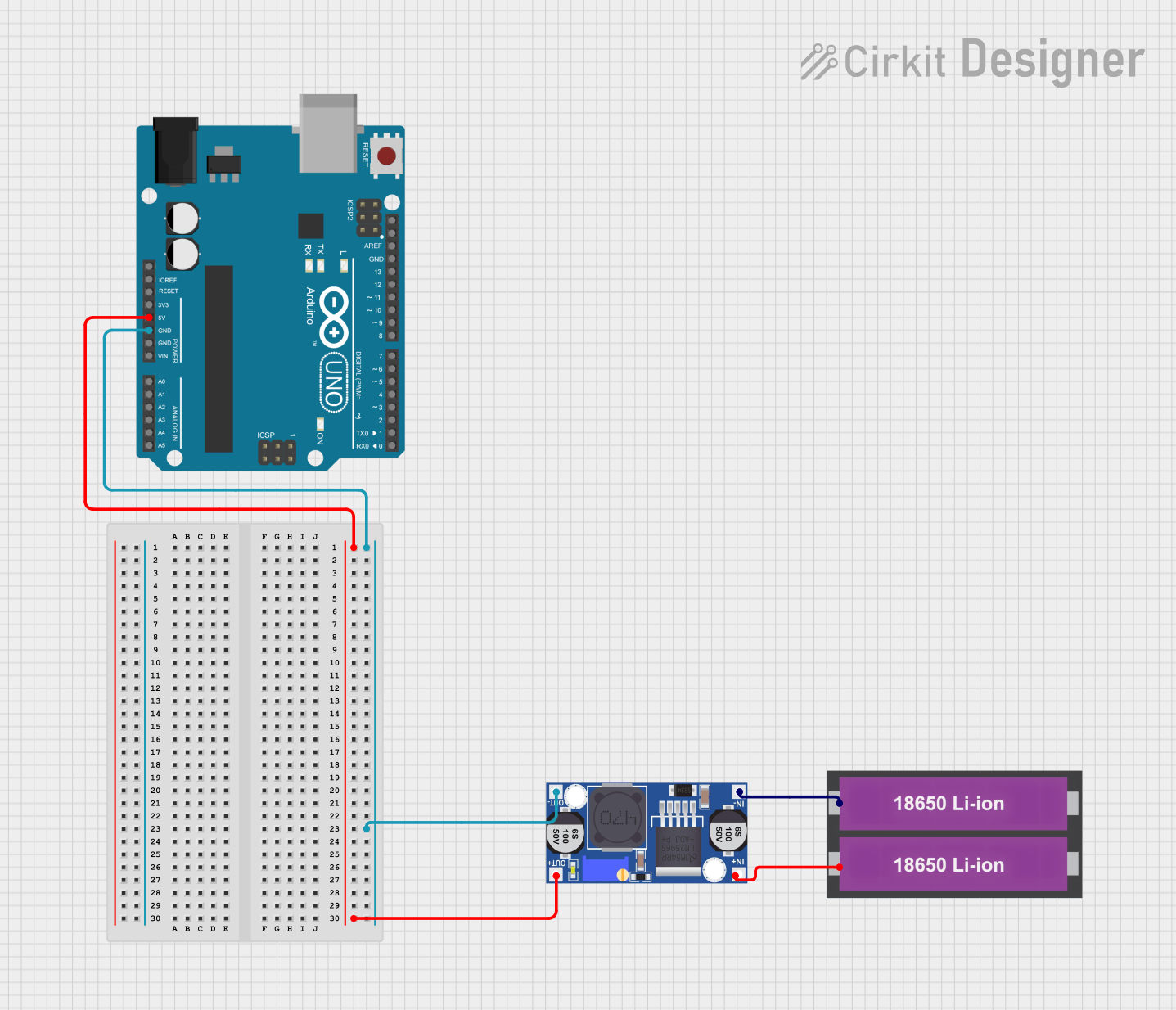
Power Supply Connection: Connect a power source with a voltage range between 2.0V and 5.5V to the VIN pin. Ensure that the power source can supply the necessary current for your application.
Ground Connection: Connect the GND pin to the ground of your power source and the ground of your load circuit.
Output Voltage: Connect the VOUT pin to the power input of your low-power electronics. This pin provides a regulated 3.3V output.
Enable Pin: The EN pin can be connected to a digital output of a microcontroller or a switch to turn the converter on or off. Pulling this pin high will enable the converter.
Power Good Indicator: The PG pin can be connected to an LED or a microcontroller input to indicate when the output voltage is within regulation.
Important Considerations and Best Practices
- Ensure that the input voltage does not exceed the maximum rating of 5.5V to prevent damage to the converter.
- Place a capacitor close to the VIN and VOUT pins to stabilize the input and output voltages and reduce noise.
- Keep the power paths as short as possible to minimize losses and improve efficiency.
- Avoid placing high-heat components near the converter to maintain thermal performance.
- Use the PG pin to monitor the health of the power supply and implement safety features in your application.
Troubleshooting and FAQs
Common Issues
- Output Voltage is Not Regulated: Check the input voltage and connections. Ensure that the input voltage is within the specified range and that all connections are secure.
- Converter is Overheating: Ensure that the current draw is within the maximum output current rating. Check for any shorts or excessive load on the output.
Solutions and Tips for Troubleshooting
- If the output voltage is not regulated, verify that the input voltage is stable and within the specified range.
- If the converter is overheating, reduce the load or improve airflow around the component.
- Use a multimeter to check for continuity and proper voltage levels at the input and output pins.
FAQs
Q: Can I adjust the output voltage of the LM3671? A: The Adafruit LM3671 comes with a fixed 3.3V output. For adjustable output versions, refer to the LM3671 datasheet for the adjustable version.
Q: What is the maximum input voltage the LM3671 can handle? A: The maximum input voltage is 5.5V. Exceeding this voltage can damage the converter.
Q: How do I know if the converter is working properly? A: The PG (Power Good) pin will go high when the output voltage is within regulation, indicating proper operation.
Example Code for Arduino UNO
Below is an example code snippet for enabling and disabling the Adafruit LM3671 using an Arduino UNO. The LM3671's EN pin is controlled by the Arduino's digital pin 7.
#define ENABLE_PIN 7 // Connect the EN pin of LM3671 to digital pin 7

void setup() {
  pinMode(ENABLE_PIN, OUTPUT);
  // Start with the buck converter enabled
  digitalWrite(ENABLE_PIN, HIGH);
}

void loop() {
  // Enable the buck converter for 5 seconds
  digitalWrite(ENABLE_PIN, HIGH);
  delay(5000);

  // Disable the buck converter for 5 seconds
  digitalWrite(ENABLE_PIN, LOW);
  delay(5000);
}
Remember to keep the code comments concise and within the 80 character line length limit. This example demonstrates a simple on-off cycle for the buck converter, which can be integrated into more complex power management schemes within your projects.