
How to Use DS18B20 Temperature: Examples, Pinouts, and Specs

 Design with DS18B20 Temperature in Cirkit Designer
Introduction
The DS18B20 is a digital temperature sensor that provides accurate temperature readings in the range of -55°C to +125°C. It communicates over a 1-Wire interface, which simplifies wiring and allows multiple sensors to be connected to a single data line. This makes the DS18B20 an excellent choice for applications requiring temperature monitoring, such as HVAC systems, weather stations, industrial equipment, and home automation projects.
Explore Projects Built with DS18B20 Temperature
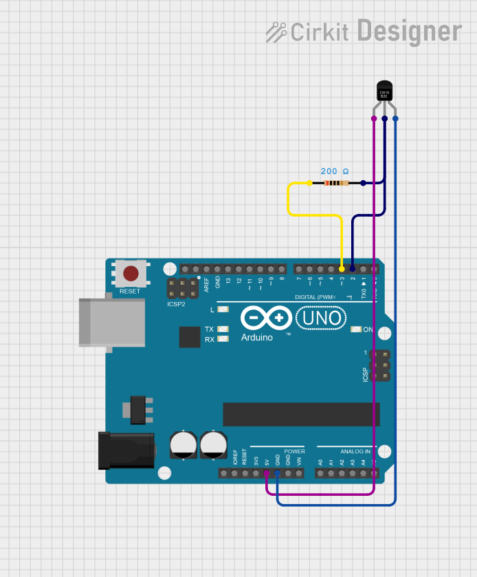 Open Project in Cirkit Designer
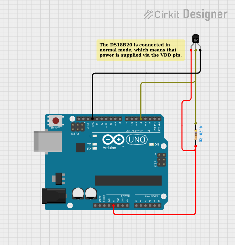 Open Project in Cirkit Designer
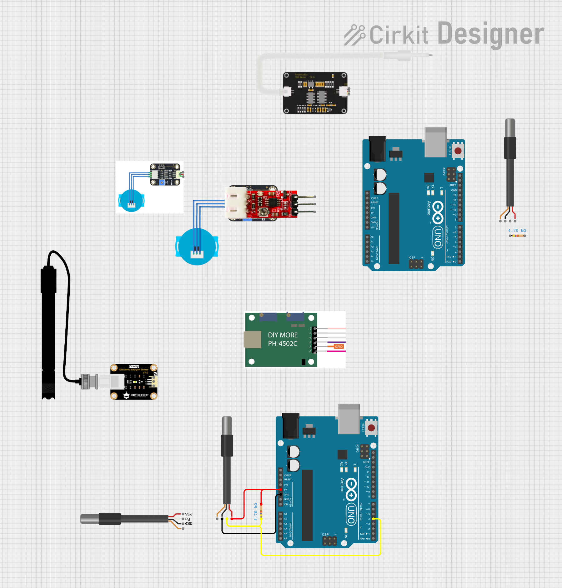 Open Project in Cirkit Designer
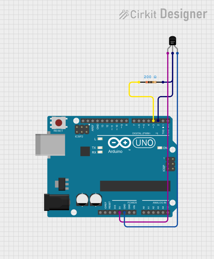 Open Project in Cirkit Designer
Explore Projects Built with DS18B20 Temperature
Open Project in Cirkit DesignerOpen Project in Cirkit DesignerOpen Project in Cirkit DesignerOpen Project in Cirkit DesignerCommon Applications:
- Environmental monitoring systems
- Industrial temperature control
- Data logging and weather stations
- Home automation and IoT projects
- Overheat protection in electronic devices
Technical Specifications
The DS18B20 is a robust and versatile sensor with the following key specifications:
| Parameter | Value |
|---|---|
| Operating Voltage | 3.0V to 5.5V |
| Temperature Range | -55°C to +125°C |
| Accuracy | ±0.5°C (from -10°C to +85°C) |
| Resolution | Programmable: 9-bit to 12-bit |
| Interface | 1-Wire |
| Maximum Current (Active) | 1.5 mA |
| Standby Current | 750 nA |
| Conversion Time | 93.75 ms (9-bit) to 750 ms (12-bit) |
| Unique 64-bit ROM Code | Yes |
Pin Configuration
The DS18B20 is available in a 3-pin TO-92 package or as a waterproof probe. Below is the pin configuration for the TO-92 package:
| Pin | Name | Description |
|---|---|---|
| 1 | GND | Ground connection |
| 2 | DQ | Data line (1-Wire communication) |
| 3 | VDD | Power supply (optional for parasitic power mode) |
Wiring Diagram
For a typical setup, connect the DS18B20 as follows:
- Pin 1 (GND) to ground
- Pin 2 (DQ) to a digital I/O pin on the microcontroller (with a pull-up resistor, typically 4.7 kΩ)
- Pin 3 (VDD) to 3.3V or 5V (optional for parasitic power mode)
Usage Instructions
How to Use the DS18B20 in a Circuit
- Powering the Sensor: The DS18B20 can operate in two modes:
- Normal Mode: Connect VDD to a 3.3V or 5V power supply.
- Parasitic Power Mode: Leave VDD unconnected, and the sensor will draw power from the data line.
- Pull-Up Resistor: A 4.7 kΩ pull-up resistor is required on the data line (DQ) to ensure proper communication.
- 1-Wire Communication: The DS18B20 communicates using a 1-Wire protocol, which requires only one data line for communication.
Example Code for Arduino UNO
Below is an example of how to interface the DS18B20 with an Arduino UNO using the DallasTemperature and OneWire libraries:
#include <OneWire.h>
#include <DallasTemperature.h>

// Pin connected to the DS18B20 data line
#define ONE_WIRE_BUS 2

// Setup a oneWire instance to communicate with any 1-Wire devices
OneWire oneWire(ONE_WIRE_BUS);

// Pass the oneWire reference to DallasTemperature library
DallasTemperature sensors(&oneWire);

void setup() {
  Serial.begin(9600); // Initialize serial communication
  sensors.begin();    // Start the DS18B20 sensor
  Serial.println("DS18B20 Temperature Sensor Example");
}

void loop() {
  sensors.requestTemperatures(); // Request temperature readings
  float temperatureC = sensors.getTempCByIndex(0); // Get temperature in Celsius
  if (temperatureC != DEVICE_DISCONNECTED_C) {
    Serial.print("Temperature: ");
    Serial.print(temperatureC);
    Serial.println(" °C");
  } else {
    Serial.println("Error: Sensor not detected!");
  }
  delay(1000); // Wait 1 second before the next reading
}
Important Considerations
- Pull-Up Resistor: Ensure the pull-up resistor is properly connected to the data line.
- Cable Length: For long cables, use a lower pull-up resistor value (e.g., 2.2 kΩ) to maintain signal integrity.
- Parasitic Power Mode: Avoid using parasitic power mode in noisy environments or with long cables, as it may cause unreliable readings.
Troubleshooting and FAQs
Common Issues and Solutions
No Temperature Reading:
- Ensure the sensor is properly connected to the circuit.
- Verify the pull-up resistor is in place and has the correct value (4.7 kΩ).
- Check the data pin connection to the microcontroller.
Incorrect Temperature Values:
- Ensure the sensor is operating within its specified voltage range (3.0V to 5.5V).
- Verify the resolution setting in the code (default is 12-bit).
Sensor Not Detected:
- Confirm the unique 64-bit ROM code is being read correctly.
- Check for loose or faulty connections in the circuit.
Interference with Multiple Sensors:
- Assign unique addresses to each sensor and ensure proper wiring.
- Use a lower pull-up resistor value for long cables or multiple sensors.
FAQs
Q: Can I connect multiple DS18B20 sensors to the same data line?
A: Yes, the DS18B20 supports multiple sensors on a single data line. Each sensor has a unique 64-bit ROM code for identification.
Q: What is the maximum cable length for the DS18B20?
A: The maximum cable length depends on the pull-up resistor value and environmental noise. Typically, lengths up to 30 meters are achievable with a 4.7 kΩ resistor.
Q: Can the DS18B20 operate without a power supply (VDD)?
A: Yes, the DS18B20 can operate in parasitic power mode, drawing power from the data line. However, this mode is less reliable in noisy environments.
Q: How do I increase the accuracy of temperature readings?
A: Use the default 12-bit resolution for maximum accuracy (±0.5°C). Lower resolutions (9-bit to 11-bit) may result in faster readings but reduced accuracy.
By following this documentation, you can effectively integrate the DS18B20 temperature sensor into your projects for reliable and accurate temperature monitoring.