How to Use Piezo Sensor Module: Examples, Pinouts, and Specs
Introduction
The Piezo Sensor Module is a device that converts mechanical stress, vibrations, or pressure into an electrical signal. It leverages the piezoelectric effect, where certain materials generate an electric charge in response to applied mechanical force. This module is widely used in applications requiring sound detection, vibration monitoring, or pressure sensing.
Explore Projects Built with Piezo Sensor Module
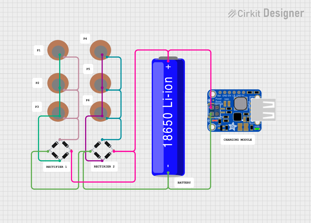
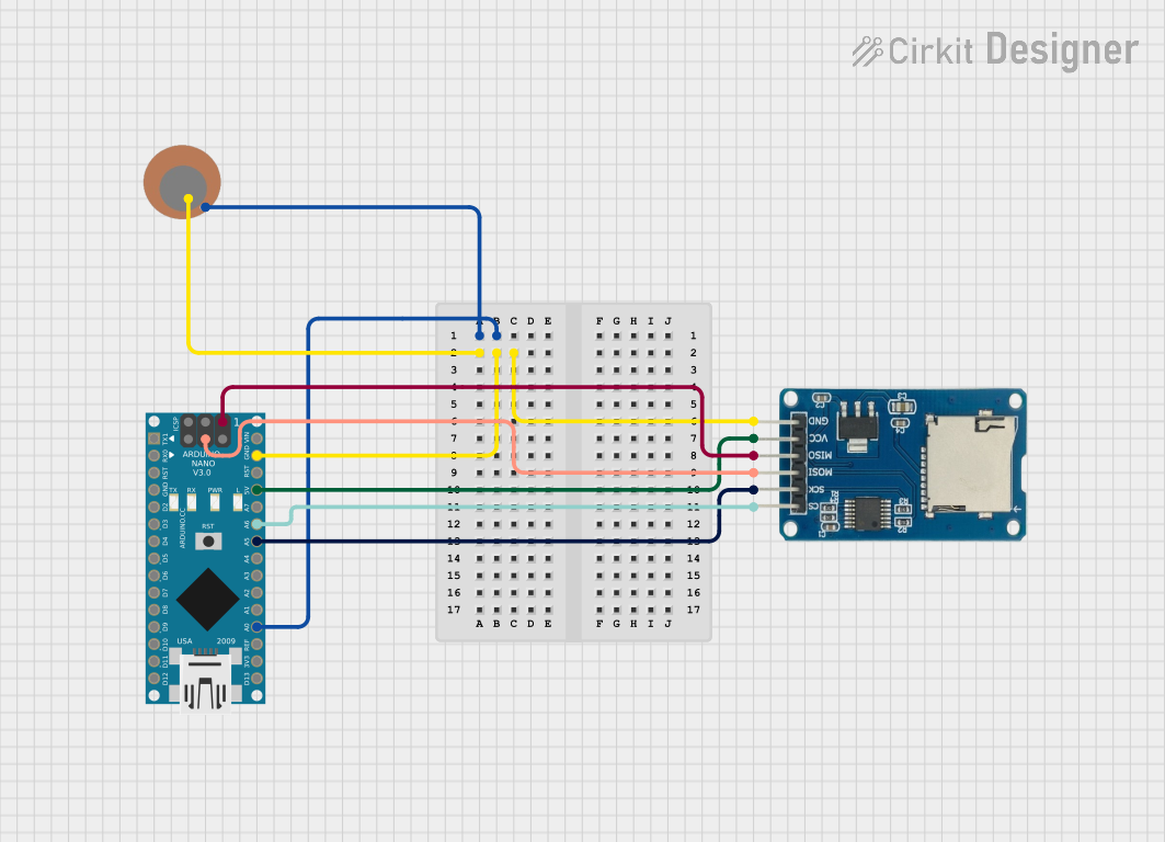
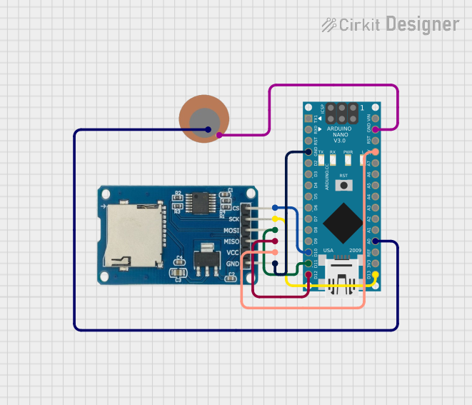
Explore Projects Built with Piezo Sensor Module
Common Applications and Use Cases
- Sound detection (e.g., claps, knocks, or other acoustic signals)
- Vibration monitoring in machinery or structures
- Pressure sensing in touch-sensitive devices
- Impact detection in robotics or security systems
- Musical instruments for sound pickup
Technical Specifications
The Piezo Sensor Module typically consists of a piezoelectric element and a signal conditioning circuit. Below are the key technical details:
| Parameter | Value |
|---|---|
| Operating Voltage | 3.3V to 5V |
| Output Signal Type | Analog or Digital (depending on module) |
| Sensitivity Range | -40 dB to -20 dB |
| Frequency Response | 1 Hz to 5 kHz |
| Operating Temperature | -20°C to 70°C |
| Dimensions | Varies by module (e.g., 30mm x 15mm) |
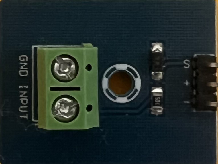
Pin Configuration and Descriptions
The Piezo Sensor Module typically has three pins:
| Pin | Name | Description |
|---|---|---|
| 1 | VCC | Power supply pin (3.3V to 5V) |
| 2 | GND | Ground connection |
| 3 | OUT | Output pin (analog or digital signal, depending on module) |
Usage Instructions
How to Use the Piezo Sensor Module in a Circuit
- Power the Module: Connect the
VCCpin to a 3.3V or 5V power source and theGNDpin to the ground. - Connect the Output: Attach the
OUTpin to an analog or digital input pin of your microcontroller (e.g., Arduino UNO). - Signal Processing: If the module outputs an analog signal, you can read it using an ADC (Analog-to-Digital Converter) pin. For digital output, the signal will be HIGH or LOW based on the detected vibration or sound.
Important Considerations and Best Practices
- Mounting: Ensure the piezo sensor is securely mounted to the surface where vibrations or pressure will be measured.
- Signal Conditioning: For analog output, you may need to filter or amplify the signal for better accuracy.
- Debouncing: If using the module for impact detection, implement software debouncing to avoid false triggers.
- Voltage Compatibility: Verify that the module's operating voltage matches your microcontroller's input voltage levels.
Example: Connecting to an Arduino UNO
Below is an example of how to use the Piezo Sensor Module with an Arduino UNO to detect vibrations and print the signal value to the Serial Monitor.
// Define the pin connected to the Piezo Sensor Module
const int piezoPin = A0; // Analog pin A0 for reading the sensor output

void setup() {
  Serial.begin(9600); // Initialize serial communication at 9600 baud
  pinMode(piezoPin, INPUT); // Set the piezo pin as an input
}

void loop() {
  int sensorValue = analogRead(piezoPin); // Read the analog value from the sensor
  Serial.print("Piezo Sensor Value: ");
  Serial.println(sensorValue); // Print the sensor value to the Serial Monitor

  delay(100); // Add a small delay to avoid overwhelming the Serial Monitor
}
Notes:
- Adjust the
delay()value in the code to control the frequency of readings. - Use a resistor in parallel with the piezo element to prevent high voltage spikes.
Troubleshooting and FAQs
Common Issues and Solutions
No Output Signal
- Cause: Loose connections or insufficient power supply.
- Solution: Check all connections and ensure the module is powered with the correct voltage.
Inconsistent Readings
- Cause: Environmental noise or improper mounting.
- Solution: Shield the module from external noise and ensure it is securely mounted.
Output Signal Too Weak
- Cause: Low sensitivity of the piezo element or weak vibrations.
- Solution: Use an amplifier circuit to boost the signal.
Arduino Not Detecting Signal
- Cause: Incorrect pin configuration or damaged module.
- Solution: Verify the pin connections and test the module with a multimeter.
FAQs
Q: Can the Piezo Sensor Module detect sound?
A: Yes, it can detect sound vibrations, but it is more sensitive to physical impacts or vibrations than airborne sound waves.
Q: Is the module waterproof?
A: Most Piezo Sensor Modules are not waterproof. If needed, use a waterproof enclosure to protect the module.
Q: Can I use this module with a Raspberry Pi?
A: Yes, the module can be used with a Raspberry Pi. Connect the output to an appropriate GPIO pin and use an ADC if the output is analog.
Q: How do I increase the sensitivity of the module?
A: You can increase sensitivity by using an amplifier circuit or adjusting the mounting to better capture vibrations.