Cirkit Designer Logo
Cirkit Designer
Your all-in-one circuit design IDE
Home / 
Component Documentation

How to Use Adafruit Precision 9-DoF LIS3MDL + LSM6DSOX: Examples, Pinouts, and Specs

Image of Adafruit Precision 9-DoF LIS3MDL + LSM6DSOX
Cirkit Designer LogoDesign with Adafruit Precision 9-DoF LIS3MDL + LSM6DSOX in Cirkit Designer

Introduction

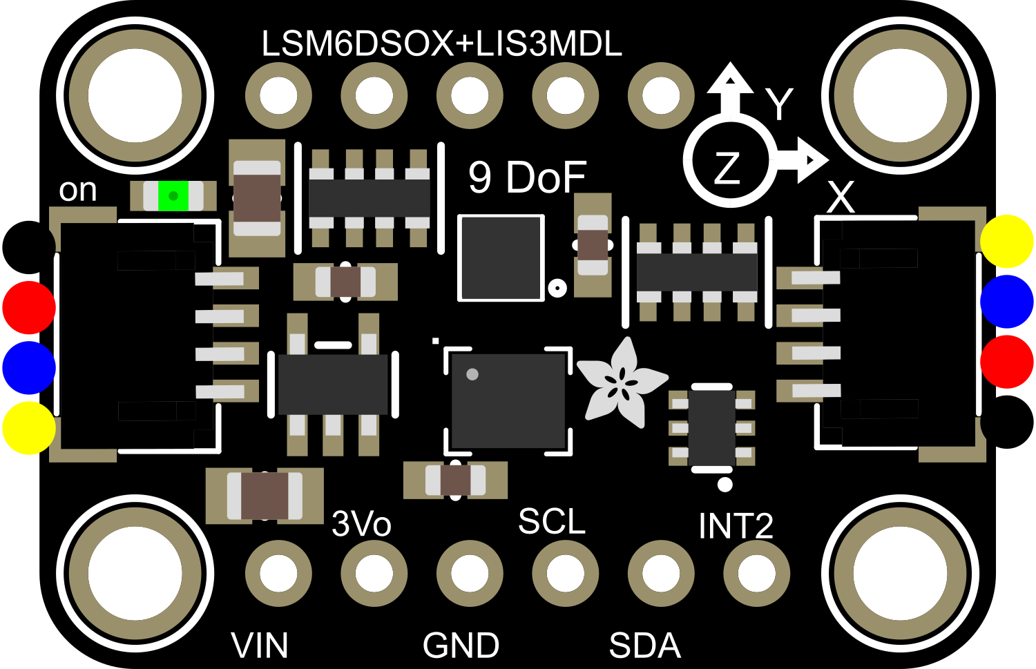
The Adafruit Precision 9-DoF (Degrees of Freedom) LIS3MDL + LSM6DSOX is a versatile and high-precision sensor module that combines a 3-axis accelerometer and a 3-axis magnetometer. This sensor is ideal for applications requiring motion sensing, orientation, and magnetic field measurements. With its low noise and high accuracy, the module is well-suited for projects in robotics, navigation, gesture recognition, and more. It is also compatible with popular development platforms such as Arduino and Raspberry Pi, allowing for easy integration into a wide range of projects.

Explore Projects Built with Adafruit Precision 9-DoF LIS3MDL + LSM6DSOX

Use Cirkit Designer to design, explore, and prototype these projects online. Some projects support real-time simulation. Click "Open Project" to start designing instantly!
Raspberry Pi 5-Based Multi-Sensor IMU System with MPU-6050 and LSM303c
Image of GRS: A project utilizing Adafruit Precision 9-DoF LIS3MDL + LSM6DSOX in a practical application
This circuit integrates a Raspberry Pi 5 with multiple sensors, including an MPU-6050 accelerometer and gyroscope, and an LSM303c 6DOF IMU, to collect and process motion and orientation data. The Raspberry Pi serves as the central processing unit, interfacing with the sensors via GPIO pins and providing power to them.
Cirkit Designer LogoOpen Project in Cirkit Designer
Arduino Mega 2560-Based Multi-Sensor System with Distance, Magnetometer, and Camera Integration
Image of Junior Design - Sensors: A project utilizing Adafruit Precision 9-DoF LIS3MDL + LSM6DSOX in a practical application
This circuit features an Arduino Mega 2560 microcontroller interfaced with multiple VL53L0X distance sensors, an OV7725 camera module, and an Adafruit LIS3MDL triple-axis magnetometer. The Arduino reads data from these sensors and the camera, likely for a robotics or environmental sensing application, and processes the data for further use or transmission.
Cirkit Designer LogoOpen Project in Cirkit Designer
Raspberry Pi Zero-Based Sensor Hub with IMU and Flex Resistor
Image of Project: A project utilizing Adafruit Precision 9-DoF LIS3MDL + LSM6DSOX in a practical application
This circuit integrates a Raspberry Pi Zero with an Adafruit ADS1115 16-bit ADC and an Adafruit BNO085 9-DOF Orientation IMU Fusion sensor. The Raspberry Pi reads analog signals from a flex resistor through the ADC and gathers orientation data from the IMU sensor, enabling it to process both analog and motion data.
Cirkit Designer LogoOpen Project in Cirkit Designer
Arduino UNO R4 WiFi and Adafruit LIS3DH Accelerometer-Based Motion Detection System
Image of circuit: A project utilizing Adafruit Precision 9-DoF LIS3MDL + LSM6DSOX in a practical application
This circuit consists of an Arduino UNO R4 WiFi connected to an Adafruit LIS3DH Triple-Axis Accelerometer via I2C communication. The Arduino reads acceleration data from the LIS3DH sensor and outputs it to the serial monitor for further analysis or processing.
Cirkit Designer LogoOpen Project in Cirkit Designer

Explore Projects Built with Adafruit Precision 9-DoF LIS3MDL + LSM6DSOX

Use Cirkit Designer to design, explore, and prototype these projects online. Some projects support real-time simulation. Click "Open Project" to start designing instantly!
Image of GRS: A project utilizing Adafruit Precision 9-DoF LIS3MDL + LSM6DSOX in a practical application
Raspberry Pi 5-Based Multi-Sensor IMU System with MPU-6050 and LSM303c
This circuit integrates a Raspberry Pi 5 with multiple sensors, including an MPU-6050 accelerometer and gyroscope, and an LSM303c 6DOF IMU, to collect and process motion and orientation data. The Raspberry Pi serves as the central processing unit, interfacing with the sensors via GPIO pins and providing power to them.
Cirkit Designer LogoOpen Project in Cirkit Designer
Image of Junior Design - Sensors: A project utilizing Adafruit Precision 9-DoF LIS3MDL + LSM6DSOX in a practical application
Arduino Mega 2560-Based Multi-Sensor System with Distance, Magnetometer, and Camera Integration
This circuit features an Arduino Mega 2560 microcontroller interfaced with multiple VL53L0X distance sensors, an OV7725 camera module, and an Adafruit LIS3MDL triple-axis magnetometer. The Arduino reads data from these sensors and the camera, likely for a robotics or environmental sensing application, and processes the data for further use or transmission.
Cirkit Designer LogoOpen Project in Cirkit Designer
Image of Project: A project utilizing Adafruit Precision 9-DoF LIS3MDL + LSM6DSOX in a practical application
Raspberry Pi Zero-Based Sensor Hub with IMU and Flex Resistor
This circuit integrates a Raspberry Pi Zero with an Adafruit ADS1115 16-bit ADC and an Adafruit BNO085 9-DOF Orientation IMU Fusion sensor. The Raspberry Pi reads analog signals from a flex resistor through the ADC and gathers orientation data from the IMU sensor, enabling it to process both analog and motion data.
Cirkit Designer LogoOpen Project in Cirkit Designer
Image of circuit: A project utilizing Adafruit Precision 9-DoF LIS3MDL + LSM6DSOX in a practical application
Arduino UNO R4 WiFi and Adafruit LIS3DH Accelerometer-Based Motion Detection System
This circuit consists of an Arduino UNO R4 WiFi connected to an Adafruit LIS3DH Triple-Axis Accelerometer via I2C communication. The Arduino reads acceleration data from the LIS3DH sensor and outputs it to the serial monitor for further analysis or processing.
Cirkit Designer LogoOpen Project in Cirkit Designer

Technical Specifications

Key Technical Details

  • Accelerometer (LSM6DSOX):

    • 3-axis linear acceleration measurements
    • Full-scale ranges: ±2/±4/±8/±16 g
    • Output data rates (ODR) up to 6.66 kHz
  • Magnetometer (LIS3MDL):

    • 3-axis magnetic field measurements
    • Full-scale ranges: ±4/±8/±12/±16 gauss
    • Output data rates (ODR) up to 155 Hz
  • Operating Voltage:

    • 2.5V to 5.5V
  • Communication:

    • I2C and SPI interfaces
  • Operating Temperature Range:

    • -40°C to +85°C

Pin Configuration and Descriptions

Pin Number Name Description
1 VIN Supply voltage (2.5V to 5.5V)
2 GND Ground
3 SCL I2C clock (also SPI clock)
4 SDA I2C data (also SPI data input)
5 SDO/SA0 SPI data output (also I2C address selection)
6 CS SPI chip select (active low)
7 INT1 Interrupt 1 (configurable)
8 INT2 Interrupt 2 (configurable)

Usage Instructions

Integration into a Circuit

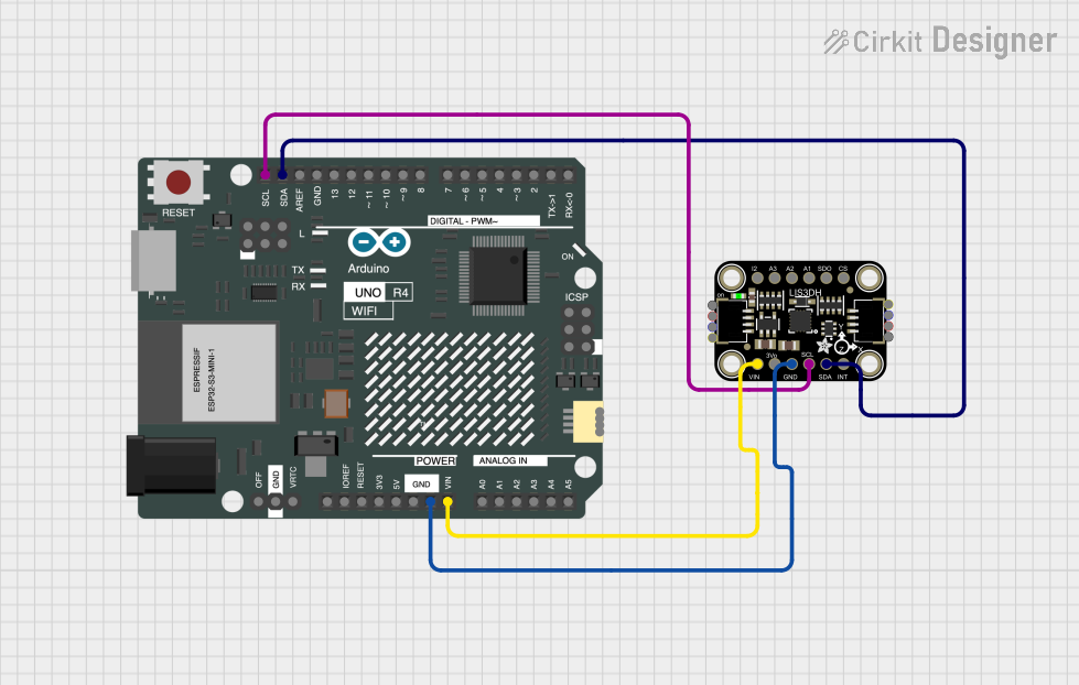
To use the Adafruit Precision 9-DoF sensor with an Arduino UNO, follow these steps:

  1. Connect VIN to the 5V output on the Arduino.
  2. Connect GND to one of the GND pins on the Arduino.
  3. Connect SCL to the A5 pin (SCL) on the Arduino.
  4. Connect SDA to the A4 pin (SDA) on the Arduino.
  5. If using SPI, connect SDO/SA0, CS, and additional SPI pins as required.

Best Practices

  • Ensure that the power supply is stable and within the specified voltage range.
  • Use pull-up resistors on the I2C lines if they are not included on the development board.
  • When using SPI, ensure that the CS pin is driven high to low before and after communication.
  • Avoid placing the sensor near strong magnetic fields to prevent interference.

Example Code for Arduino

#include <Wire.h>
#include <Adafruit_Sensor.h>
#include <Adafruit_LSM6DSOX.h>
#include <Adafruit_LIS3MDL.h>

// Create sensor instances
Adafruit_LSM6DSOX sox;
Adafruit_LIS3MDL mdl;

void setup() {
  Serial.begin(115200);
  // Initialize the sensors
  if (!sox.begin_I2C()) {
    Serial.println("Failed to find LSM6DSOX chip");
    while (1) { delay(10); }
  }
  if (!mdl.begin_I2C()) {
    Serial.println("Failed to find LIS3MDL chip");
    while (1) { delay(10); }
  }
  Serial.println("LSM6DSOX and LIS3MDL sensors found!");
}

void loop() {
  // Read accelerometer and magnetometer values
  sensors_event_t accel, gyro, mag, temp;
  sox.getEvent(&accel, &gyro, &temp);
  mdl.getEvent(&mag);

  // Print the values to the Serial Monitor
  Serial.print("Accel X: "); Serial.print(accel.acceleration.x); Serial.print(" m/s^2");
  Serial.print(" Y: "); Serial.print(accel.acceleration.y); Serial.print(" m/s^2");
  Serial.print(" Z: "); Serial.print(accel.acceleration.z); Serial.println(" m/s^2");

  Serial.print("Mag X: "); Serial.print(mag.magnetic.x); Serial.print(" uT");
  Serial.print(" Y: "); Serial.print(mag.magnetic.y); Serial.print(" uT");
  Serial.print(" Z: "); Serial.print(mag.magnetic.z); Serial.println(" uT");

  delay(100);
}

Troubleshooting and FAQs

Common Issues

  • Sensor not detected: Ensure that the wiring is correct and that the sensor is properly powered.
  • Inaccurate readings: Calibrate the sensor and make sure it is not affected by nearby magnetic fields.
  • No data on Serial Monitor: Check the baud rate and the USB connection to the Arduino.

FAQs

Q: Can I use this sensor with a 3.3V system? A: Yes, the sensor can operate at voltages as low as 2.5V.

Q: How do I change the I2C address? A: The I2C address can be changed by connecting the SDO/SA0 pin to either ground or VIN.

Q: What is the maximum sampling rate? A: The accelerometer can sample up to 6.66 kHz, and the magnetometer up to 155 Hz.

For further assistance, consult the Adafruit support forums or the community resources available for your development platform.