How to Use Mux Shield 2: Examples, Pinouts, and Specs
Introduction
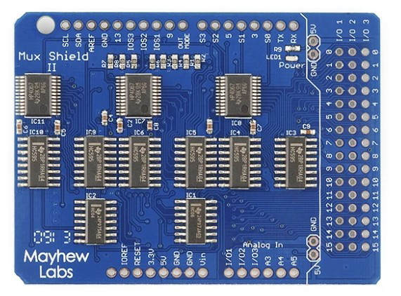
The Mux Shield 2 (Manufacturer Part ID: DEV-11723) by Mayhew Labs is a multiplexer shield designed for Arduino boards. It allows multiple signals to be routed through a single pin, significantly expanding the number of inputs and outputs available for your projects. This shield is ideal for applications requiring a large number of analog or digital I/O connections, such as sensor arrays, LED matrices, or complex control systems.
Explore Projects Built with Mux Shield 2
Explore Projects Built with Mux Shield 2
Common Applications and Use Cases
- Expanding the number of analog or digital inputs/outputs on an Arduino.
- Reading data from large sensor arrays.
- Controlling LED matrices or other multi-channel devices.
- Efficiently managing I/O resources in robotics and automation projects.
Technical Specifications
The Mux Shield 2 is built to simplify the process of multiplexing signals. Below are its key technical details:
Key Specifications
- Operating Voltage: 5V (powered by the Arduino board).
- Multiplexing Channels:
- 48 channels (16 channels per multiplexer, 3 multiplexers in total).
- Signal Types: Supports both analog and digital signals.
- Control Pins: Uses 3 Arduino pins for channel selection.
- Compatibility: Designed for Arduino Uno, Mega, and other compatible boards.
- Dimensions: Standard Arduino shield form factor.
Pin Configuration and Descriptions
The Mux Shield 2 uses the following pin configuration for operation:
Control Pins
| Arduino Pin | Function | Description |
|---|---|---|
| D2 | S0 | Multiplexer channel select bit 0 |
| D3 | S1 | Multiplexer channel select bit 1 |
| D4 | S2 | Multiplexer channel select bit 2 |
Multiplexer Channels
| Multiplexer | Channels | Arduino Pin |
|---|---|---|
| MUX1 | CH0 - CH15 | A0 (default input/output pin for MUX1) |
| MUX2 | CH0 - CH15 | A1 (default input/output pin for MUX2) |
| MUX3 | CH0 - CH15 | A2 (default input/output pin for MUX3) |
Note: The shield uses Arduino analog pins A0, A1, and A2 as the default I/O pins for the three multiplexers. These can be reconfigured if needed.
Usage Instructions
The Mux Shield 2 is straightforward to use with Arduino. Follow these steps to integrate it into your project:
Step 1: Hardware Setup
- Attach the Mux Shield 2 to your Arduino board by aligning the headers and pressing it into place.
- Connect your input or output devices (e.g., sensors, LEDs) to the appropriate multiplexer channels (CH0-CH15) on the shield.
- Ensure your Arduino is powered via USB or an external power source.
Step 2: Software Setup
To control the Mux Shield 2, you need to select the desired channel on each multiplexer using the control pins (S0, S1, S2). Below is an example Arduino sketch to read an analog sensor connected to channel 5 of MUX1:
// Mux Shield 2 Example: Reading an analog sensor on MUX1, channel 5

// Define control pins for the Mux Shield 2
const int S0 = 2; // Channel select bit 0
const int S1 = 3; // Channel select bit 1
const int S2 = 4; // Channel select bit 2

// Define the multiplexer input pin
const int MUX1_PIN = A0; // Default input pin for MUX1

// Function to select a channel on the multiplexer
void selectChannel(int channel) {
  digitalWrite(S0, channel & 0x01); // Set S0 based on bit 0 of the channel
  digitalWrite(S1, (channel >> 1) & 0x01); // Set S1 based on bit 1 of the channel
  digitalWrite(S2, (channel >> 2) & 0x01); // Set S2 based on bit 2 of the channel
}

void setup() {
  // Initialize control pins as outputs
  pinMode(S0, OUTPUT);
  pinMode(S1, OUTPUT);
  pinMode(S2, OUTPUT);

  // Initialize serial communication for debugging
  Serial.begin(9600);
}

void loop() {
  // Select channel 5 on MUX1
  selectChannel(5);

  // Read the analog value from the selected channel
  int sensorValue = analogRead(MUX1_PIN);

  // Print the sensor value to the Serial Monitor
  Serial.print("Channel 5 Value: ");
  Serial.println(sensorValue);

  // Wait for a short period before the next reading
  delay(500);
}
Important Considerations and Best Practices
- Signal Interference: Avoid long wires or high-frequency signals to minimize interference.
- Power Supply: Ensure your Arduino board can supply sufficient current for all connected devices.
- Channel Selection Timing: Allow a brief delay after switching channels to ensure stable readings.
- Analog vs. Digital Signals: Verify that the connected devices are compatible with the selected signal type.
Troubleshooting and FAQs
Common Issues and Solutions
Issue: Incorrect or unstable readings from the multiplexer.
- Solution: Double-check the wiring and ensure the correct channel is selected in your code. Add a small delay after switching channels to stabilize the signal.
Issue: Some channels are not responding.
- Solution: Verify that the connected devices are functional and properly wired. Ensure the control pins (S0, S1, S2) are correctly defined in your code.
Issue: Arduino resets or behaves erratically.
- Solution: Check the power supply. If multiple devices are connected, ensure the Arduino can provide sufficient current.
FAQs
Q: Can I use the Mux Shield 2 with an Arduino Mega?
A: Yes, the Mux Shield 2 is compatible with Arduino Mega. Ensure the control pins (D2, D3, D4) are not used by other peripherals.Q: Can I use the shield for both analog and digital signals simultaneously?
A: Yes, but you must configure the Arduino pins and connected devices accordingly.Q: How many devices can I connect to the Mux Shield 2?
A: You can connect up to 48 devices (16 per multiplexer).
By following this documentation, you can effectively integrate the Mux Shield 2 into your projects and expand the I/O capabilities of your Arduino board.