
Cirkit Designer
Your all-in-one circuit design IDE
Home /
Component Documentation
How to Use BLDC Brushless Fan Motor 5 inch: Examples, Pinouts, and Specs
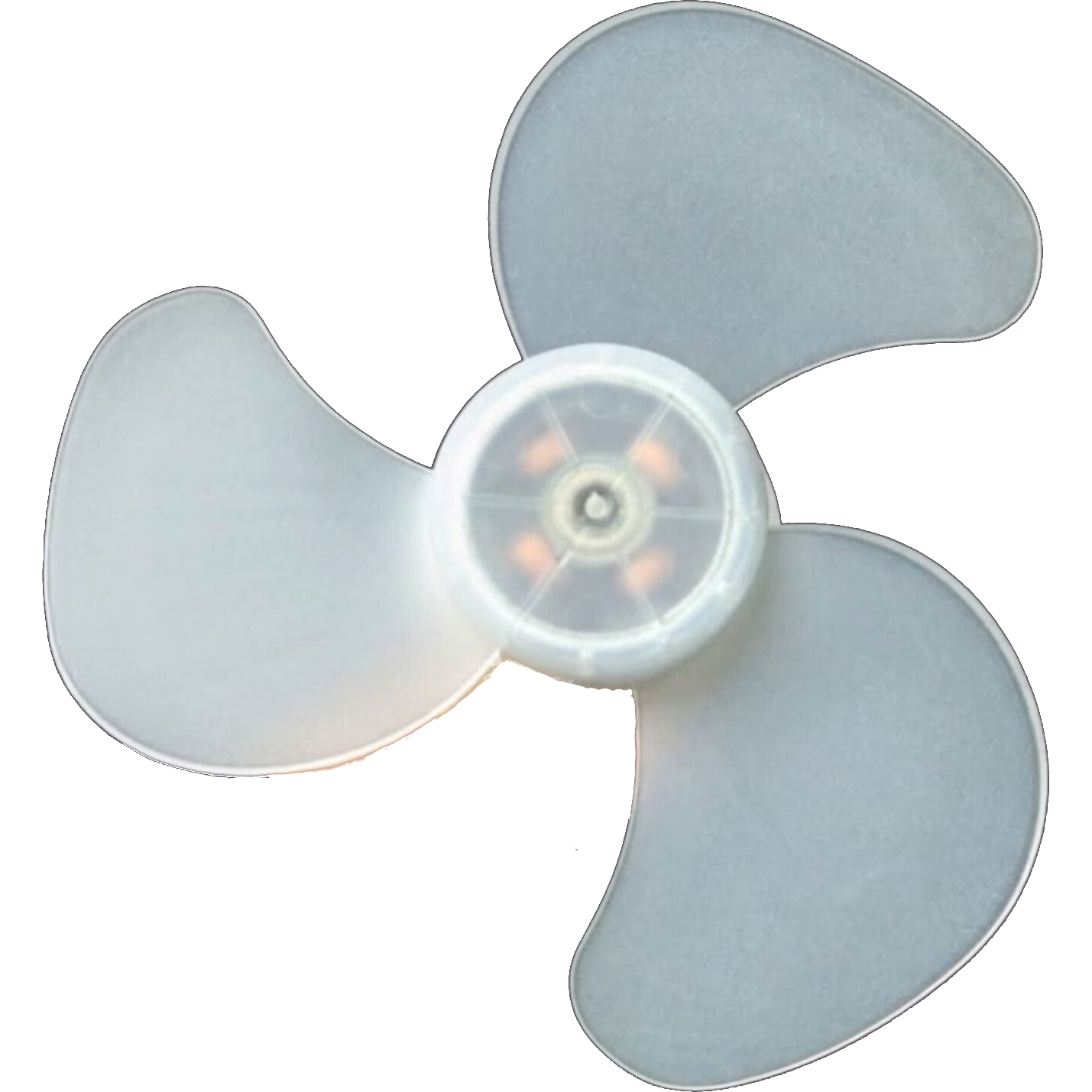
 Design with BLDC Brushless Fan Motor 5 inch in Cirkit Designer
Introduction
The 5-inch Brushless Direct Current (BLDC) Fan Motor is a highly efficient and durable motor designed for cooling applications. Unlike traditional brushed motors, this BLDC motor operates without brushes, resulting in reduced wear and tear, quieter operation, and a longer lifespan. Its compact size and high performance make it ideal for use in electronics cooling, household appliances, and industrial equipment.
Explore Projects Built with BLDC Brushless Fan Motor 5 inch
Raspberry Pi-Controlled Drone with Brushless Motors and Camera Module
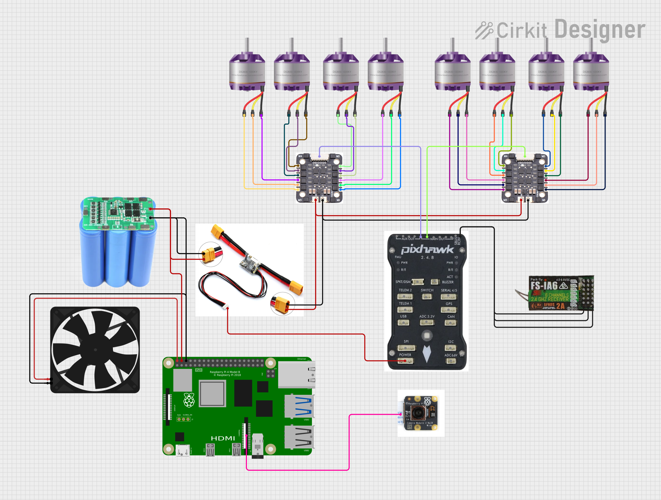
This circuit is designed for a multi-motor application, likely a drone or a similar vehicle, featuring eight brushless motors controlled by two 4-in-1 electronic speed controllers (ESCs). The ESCs are powered by a 3s2p 18650 battery pack and interfaced with a Pixhawk flight controller for motor management. Additionally, the system includes a Raspberry Pi 4B for advanced processing and control, which is connected to a NoIR camera module and a cooling fan, and a power module to supply and monitor the power to the Pixhawk.
Open Project in Cirkit DesignerQuadcopter BLDC Motor Control System with Radio Receiver
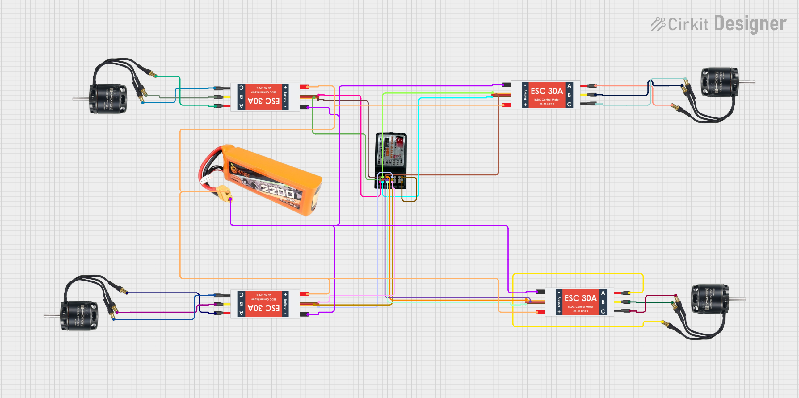
This circuit is designed to control four Brushless DC (BLDC) motors using corresponding Electronic Speed Controllers (ESCs). Each ESC receives power from a shared LiPo battery and control signals from an FS-CT6B receiver, which likely receives input from a remote transmitter for wireless control. The ESCs regulate the power supplied to the motors based on the received signals, enabling precise speed and direction control of the motors, typically used in applications such as drones or remote-controlled vehicles.
Open Project in Cirkit DesignerArduino UNO Controlled BLDC Motor Stabilization System with MPU-6050 IMU
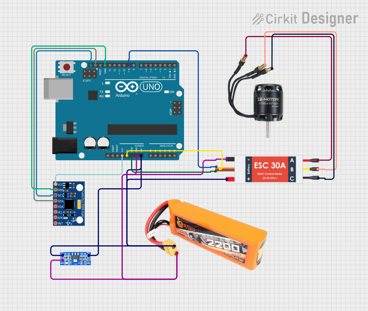
This circuit is designed to control a brushless DC (BLDC) motor using an Arduino UNO microcontroller and an Electronic Speed Controller (ESC). The Arduino reads orientation data from an MPU-6050 inertial measurement unit (IMU) and adjusts the motor's speed to stabilize a system, likely a reaction flywheel stabilization system. Power is supplied by a lipo battery, with voltage regulation provided by an AMS1117 voltage regulator.
Open Project in Cirkit DesignerSTM32H7 Controlled Brushless Motors with AS5048 Encoders and CAN Bus Communication
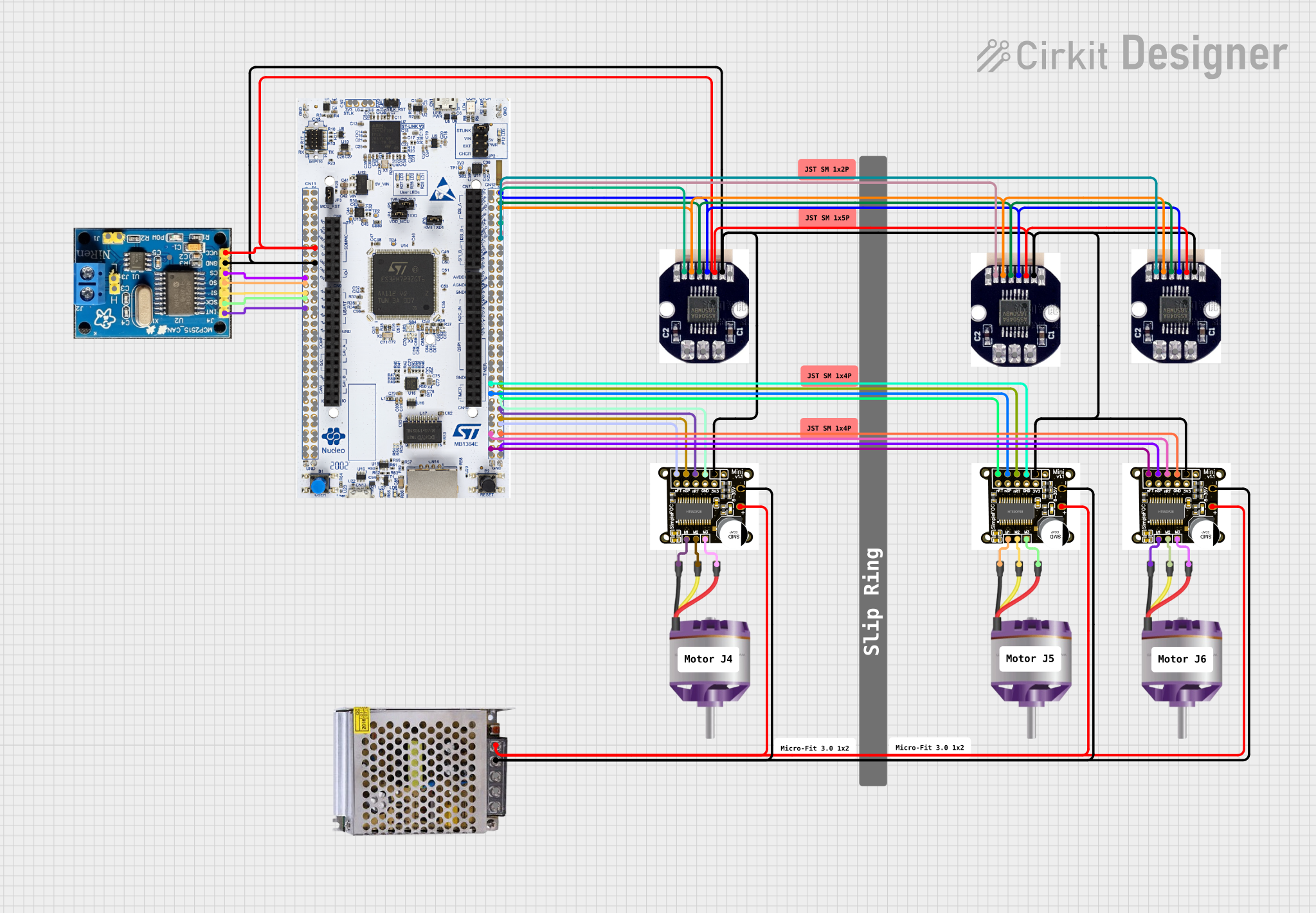
This is a motor control system designed to operate and manage multiple brushless motors with feedback from magnetic encoders. It uses a STM32H7 microcontroller for control logic, SimpleFOCMini drivers for motor control, and a CAN BUS for communication, all powered by a 12V DC supply.
Open Project in Cirkit DesignerExplore Projects Built with BLDC Brushless Fan Motor 5 inch
Raspberry Pi-Controlled Drone with Brushless Motors and Camera Module
This circuit is designed for a multi-motor application, likely a drone or a similar vehicle, featuring eight brushless motors controlled by two 4-in-1 electronic speed controllers (ESCs). The ESCs are powered by a 3s2p 18650 battery pack and interfaced with a Pixhawk flight controller for motor management. Additionally, the system includes a Raspberry Pi 4B for advanced processing and control, which is connected to a NoIR camera module and a cooling fan, and a power module to supply and monitor the power to the Pixhawk.
Open Project in Cirkit DesignerQuadcopter BLDC Motor Control System with Radio Receiver
This circuit is designed to control four Brushless DC (BLDC) motors using corresponding Electronic Speed Controllers (ESCs). Each ESC receives power from a shared LiPo battery and control signals from an FS-CT6B receiver, which likely receives input from a remote transmitter for wireless control. The ESCs regulate the power supplied to the motors based on the received signals, enabling precise speed and direction control of the motors, typically used in applications such as drones or remote-controlled vehicles.
Open Project in Cirkit DesignerArduino UNO Controlled BLDC Motor Stabilization System with MPU-6050 IMU
This circuit is designed to control a brushless DC (BLDC) motor using an Arduino UNO microcontroller and an Electronic Speed Controller (ESC). The Arduino reads orientation data from an MPU-6050 inertial measurement unit (IMU) and adjusts the motor's speed to stabilize a system, likely a reaction flywheel stabilization system. Power is supplied by a lipo battery, with voltage regulation provided by an AMS1117 voltage regulator.
Open Project in Cirkit DesignerSTM32H7 Controlled Brushless Motors with AS5048 Encoders and CAN Bus Communication
This is a motor control system designed to operate and manage multiple brushless motors with feedback from magnetic encoders. It uses a STM32H7 microcontroller for control logic, SimpleFOCMini drivers for motor control, and a CAN BUS for communication, all powered by a 12V DC supply.
Open Project in Cirkit DesignerCommon Applications:
- Cooling systems for computers, servers, and other electronics
- Ventilation in household appliances such as air purifiers and refrigerators
- Industrial equipment requiring efficient airflow
- Automotive applications, including HVAC systems
Technical Specifications
Key Technical Details:
| Parameter | Value |
|---|---|
| Motor Type | Brushless DC (BLDC) |
| Diameter | 5 inches |
| Operating Voltage Range | 12V to 24V DC |
| Rated Current | 0.5A to 1.2A (depending on load) |
| Power Consumption | 6W to 28W |
| Speed | 1500 to 3000 RPM (adjustable) |
| Airflow | Up to 120 CFM |
| Noise Level | < 35 dB |
| Lifespan | > 50,000 hours |
| Operating Temperature | -10°C to 70°C |
Pin Configuration and Descriptions:
| Pin Number | Pin Name | Description |
|---|---|---|
| 1 | VCC | Positive power supply input (12V to 24V DC). |
| 2 | GND | Ground connection. |
| 3 | PWM Input | Pulse Width Modulation (PWM) signal input for speed control (0-100% duty). |
| 4 | Tach Output | Tachometer output for speed monitoring (provides pulses proportional to RPM). |
Usage Instructions
How to Use the BLDC Fan Motor in a Circuit:
- Power Supply: Connect the VCC pin to a DC power source within the operating voltage range (12V to 24V). Ensure the power supply can provide sufficient current for the motor's operation.
- Ground Connection: Connect the GND pin to the ground of the power supply and the circuit.
- Speed Control: Use a PWM signal (typically 25 kHz) on the PWM Input pin to control the motor speed. A 0% duty cycle stops the motor, while a 100% duty cycle runs it at maximum speed.
- Speed Monitoring: Connect the Tach Output pin to a microcontroller or monitoring device to measure the motor's RPM. Each pulse corresponds to a specific number of rotations.
Important Considerations:
- Voltage Compatibility: Ensure the power supply voltage matches the motor's operating range to avoid damage.
- PWM Signal: Use a stable PWM signal for precise speed control. Avoid abrupt changes in duty cycle to prevent motor stress.
- Cooling: While the motor is efficient, ensure adequate ventilation around it to maintain optimal performance.
- Polarity: Double-check the polarity of the power connections to prevent damage to the motor.
Example: Connecting to an Arduino UNO
Below is an example of how to control the BLDC fan motor using an Arduino UNO:
// Example code to control a 5-inch BLDC fan motor using PWM on Arduino UNO

const int pwmPin = 9; // PWM output pin connected to the motor's PWM Input pin
const int tachPin = 2; // Tachometer input pin connected to the motor's Tach Output pin

volatile int tachCount = 0; // Variable to store tachometer pulse count

void setup() {
  pinMode(pwmPin, OUTPUT); // Set PWM pin as output
  pinMode(tachPin, INPUT_PULLUP); // Set Tach pin as input with pull-up resistor

  // Attach interrupt to count tachometer pulses
  attachInterrupt(digitalPinToInterrupt(tachPin), countTachPulses, FALLING);

  Serial.begin(9600); // Initialize serial communication for debugging
}

void loop() {
  // Set motor speed using PWM (0 to 255 corresponds to 0% to 100% duty cycle)
  analogWrite(pwmPin, 128); // 50% duty cycle for medium speed

  // Calculate RPM based on tachometer pulses
  int rpm = calculateRPM();
  Serial.print("Motor RPM: ");
  Serial.println(rpm);

  delay(1000); // Wait for 1 second before updating RPM
}

// Interrupt service routine to count tachometer pulses
void countTachPulses() {
  tachCount++;
}

// Function to calculate RPM based on tachometer pulses
int calculateRPM() {
  noInterrupts(); // Disable interrupts to read tachCount safely
  int pulses = tachCount;
  tachCount = 0; // Reset pulse count
  interrupts(); // Re-enable interrupts

  // Assuming 2 pulses per revolution, calculate RPM
  return (pulses * 60) / 2;
}
Notes:
- Adjust the
analogWritevalue to control the motor speed. - Ensure the tachometer pulse count matches the motor's specifications (e.g., 2 pulses per revolution).
Troubleshooting and FAQs
Common Issues:
Motor Does Not Start:
- Cause: Incorrect power supply voltage or insufficient current.
- Solution: Verify the power supply voltage and current rating. Ensure proper connections.
Motor Runs Erratically:
- Cause: Unstable PWM signal or noise in the circuit.
- Solution: Use a stable PWM source and ensure proper grounding.
No Tachometer Output:
- Cause: Incorrect connection or damaged tachometer pin.
- Solution: Check the connection to the Tach Output pin. Test with a multimeter or oscilloscope.
Overheating:
- Cause: Prolonged operation at high speed without adequate ventilation.
- Solution: Ensure proper airflow around the motor and reduce speed if necessary.
FAQs:
Q: Can I run the motor without a PWM signal?
- A: Yes, the motor will run at full speed if the PWM Input pin is left unconnected or set to 100% duty cycle.
Q: What is the maximum cable length for the PWM signal?
- A: For reliable operation, keep the PWM signal cable length under 1 meter. Use shielded cables for longer distances.
Q: Can I use this motor with a 5V power supply?
- A: No, the motor requires a minimum of 12V DC to operate.
Q: How do I clean the motor?
- A: Use compressed air to remove dust. Avoid using liquids or solvents that may damage internal components.