How to Use Module 2 Digit 7-Segment 74H595: Examples, Pinouts, and Specs
Introduction
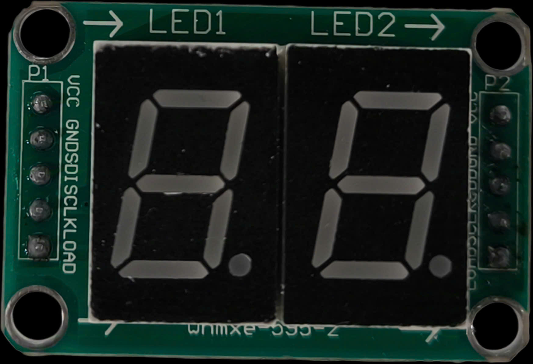
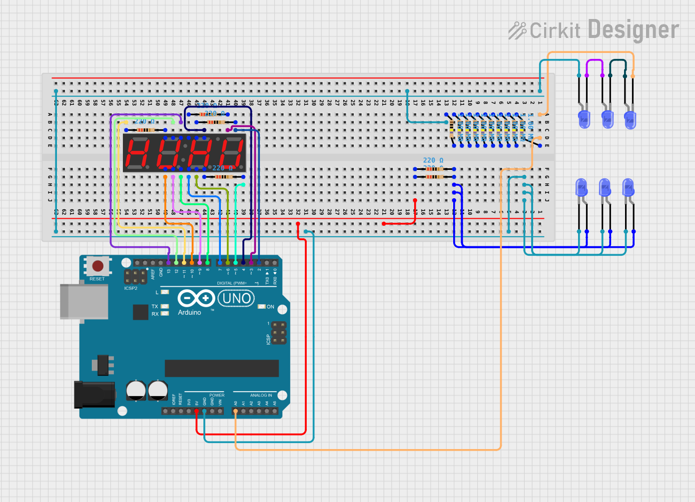
The Module 2 Digit 7-Segment 74H595 is a display module that features two 7-segment digits controlled by a 74H595 shift register. This module simplifies the process of interfacing with microcontrollers, such as Arduino, to display numerical values. By utilizing the 74H595 shift register, the module reduces the number of pins required for control, making it ideal for projects with limited GPIO availability.
Explore Projects Built with Module 2 Digit 7-Segment 74H595
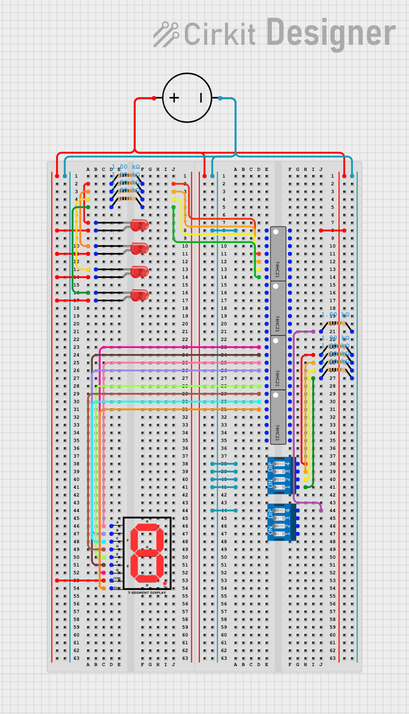
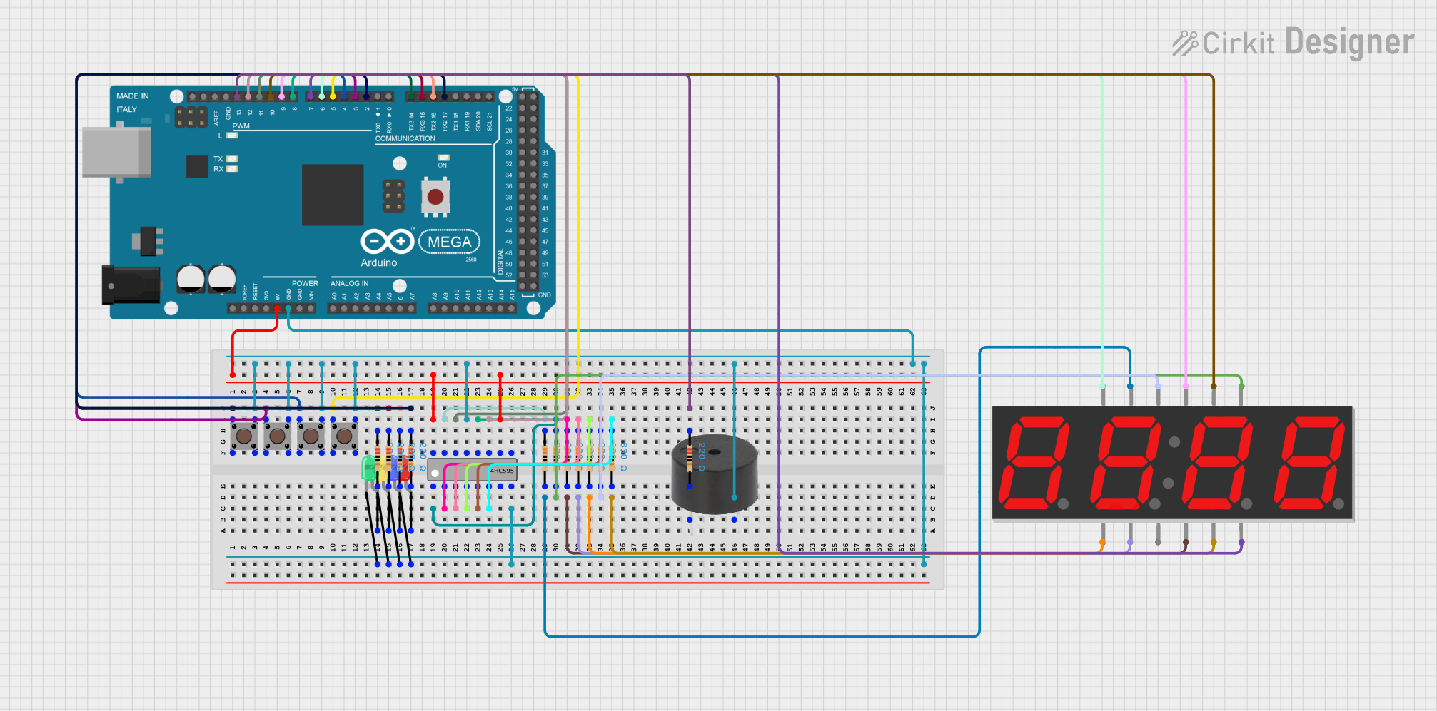
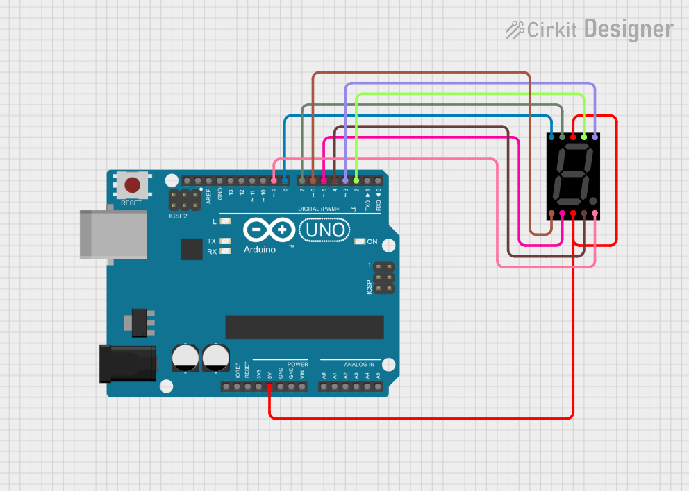
Explore Projects Built with Module 2 Digit 7-Segment 74H595
Common Applications and Use Cases
- Digital clocks and timers
- Counter displays
- Temperature or sensor value displays
- DIY electronics projects requiring numerical output
- Educational tools for learning about shift registers and displays
Technical Specifications
Key Technical Details
- Operating Voltage: 5V DC
- Current Consumption: ~20mA per segment (depending on the number of active LEDs)
- Control Interface: Serial-in, parallel-out via 74H595 shift register
- Number of Digits: 2 (7-segment displays)
- LED Type: Common cathode
- Dimensions: Varies by module, typically ~50mm x 20mm
- Operating Temperature: -40°C to 85°C
Pin Configuration and Descriptions
The module typically has 4 to 6 pins for interfacing. Below is a common pinout:
| Pin | Name | Description |
|---|---|---|
| 1 | VCC | Power supply input (5V DC). |
| 2 | GND | Ground connection. |
| 3 | DATA (DS) | Serial data input for the 74H595 shift register. |
| 4 | LATCH (ST_CP) | Latch pin to transfer data from the shift register to the output register. |
| 5 | CLOCK (SH_CP) | Clock pin to shift data into the 74H595 shift register. |
| 6 | OE (Optional) | Output enable pin (active low, often tied to GND for continuous operation). |
Note: Some modules may omit the OE pin or have it internally connected to GND.
Usage Instructions
How to Use the Component in a Circuit
- Power the Module: Connect the VCC pin to a 5V power source and the GND pin to ground.
- Connect Control Pins:
- Connect the
DATA,LATCH, andCLOCKpins to the corresponding GPIO pins on your microcontroller. - If the module has an
OEpin, connect it to GND or control it via a GPIO pin for enabling/disabling the display.
- Connect the
- Send Data: Use the 74H595 shift register protocol to send serial data to the module. Each 8-bit data packet corresponds to the segments of one digit.
- Latch the Data: Toggle the
LATCHpin to transfer the shifted data to the display.
Important Considerations and Best Practices
- Current Limiting: Ensure that the module has built-in current-limiting resistors. If not, add external resistors to prevent overdriving the LEDs.
- Refresh Rate: For smooth display updates, ensure a refresh rate of at least 60Hz.
- Power Supply: Use a stable 5V power source to avoid flickering or dimming of the display.
- Data Timing: Follow the timing requirements of the 74H595 shift register for reliable operation.
Example Code for Arduino UNO
Below is an example of how to control the module using an Arduino UNO:
// Pin definitions for the 2-digit 7-segment module
#define DATA_PIN 8    // Connect to DATA (DS) pin of the module
#define LATCH_PIN 9   // Connect to LATCH (ST_CP) pin of the module
#define CLOCK_PIN 10  // Connect to CLOCK (SH_CP) pin of the module

// Function to send data to the 74H595 shift register
void sendData(byte data) {
  digitalWrite(LATCH_PIN, LOW);  // Disable latch to prepare for data
  shiftOut(DATA_PIN, CLOCK_PIN, MSBFIRST, data);  // Send data to shift register
  digitalWrite(LATCH_PIN, HIGH); // Enable latch to update display
}

void setup() {
  // Set pin modes
  pinMode(DATA_PIN, OUTPUT);
  pinMode(LATCH_PIN, OUTPUT);
  pinMode(CLOCK_PIN, OUTPUT);

  // Initialize display (clear all segments)
  sendData(0x00);  // Turn off all segments
}

void loop() {
  // Example: Display the number "12" on the module
  byte digit1 = 0b01100000; // Binary for "1" (segments B and C on)
  byte digit2 = 0b11011010; // Binary for "2" (segments A, B, G, E, D on)

  sendData(digit1);  // Send data for the first digit
  delay(500);        // Wait for 500ms
  sendData(digit2);  // Send data for the second digit
  delay(500);        // Wait for 500ms
}
Note: The binary values for each digit depend on the specific segment mapping of your module. Refer to the module's datasheet for accurate segment-to-bit mapping.
Troubleshooting and FAQs
Common Issues and Solutions
Display Not Lighting Up:
- Check the power connections (VCC and GND).
- Verify that the
OEpin is connected to GND or properly controlled. - Ensure the microcontroller is sending data to the module.
Incorrect Digits Displayed:
- Verify the binary data being sent matches the segment mapping of your module.
- Check for timing issues in the
CLOCKandLATCHsignals.
Flickering Display:
- Ensure a stable 5V power supply.
- Increase the refresh rate of the display updates.
One Digit Not Working:
- Check the data being sent to the shift register.
- Inspect the module for damaged connections or LEDs.
FAQs
Q: Can I use this module with a 3.3V microcontroller?
A: The 74H595 shift register typically requires 5V logic levels. Use a level shifter or ensure the module is compatible with 3.3V logic.
Q: How many modules can I daisy-chain?
A: The 74H595 allows daisy-chaining multiple modules by connecting the Q7 (serial out) pin of one module to the DATA pin of the next. The number of modules depends on your microcontroller's memory and timing constraints.
Q: Do I need external resistors for the LEDs?
A: Many modules include built-in resistors. If your module does not, you must add external resistors to limit the current through the LEDs.
Q: Can I display letters or symbols?
A: Yes, but the 7-segment display is limited to simple alphanumeric characters and symbols. Refer to the segment mapping for custom patterns.