How to Use VL53LOX: Examples, Pinouts, and Specs
Introduction
The VL53LOX, manufactured by STM (part ID: CJVL53LOXV3), is a time-of-flight (ToF) distance sensor that utilizes laser technology to measure distances with high accuracy. This compact and efficient sensor can measure distances ranging from 30 mm to 2 meters, making it ideal for applications requiring precise distance measurement.
Common applications include:
- Robotics for obstacle detection and navigation
- Drones for altitude measurement and collision avoidance
- Industrial automation for object detection
- Consumer electronics for gesture recognition and proximity sensing
Explore Projects Built with VL53LOX


Explore Projects Built with VL53LOX
Technical Specifications
The VL53LOX is designed to deliver reliable and accurate distance measurements in a variety of environments. Below are its key technical details:
Key Specifications
| Parameter | Value |
|---|---|
| Operating Voltage | 2.6 V to 3.5 V |
| Communication Interface | I2C |
| Measurement Range | 30 mm to 2000 mm |
| Accuracy | ±3% |
| Field of View (FoV) | 25° |
| Operating Temperature | -20°C to +70°C |
| Power Consumption | 20 mW (typical) |
| Dimensions | 4.4 mm x 2.4 mm x 1.0 mm |
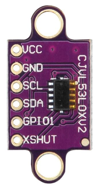
Pin Configuration
The VL53LOX has a simple pinout for easy integration into circuits. Below is the pin configuration:
| Pin Name | Pin Number | Description |
|---|---|---|
| VIN | 1 | Power supply input (2.6 V to 3.5 V) |
| GND | 2 | Ground connection |
| SDA | 3 | I2C data line |
| SCL | 4 | I2C clock line |
| XSHUT | 5 | Shutdown pin (active low) |
| GPIO1 | 6 | Interrupt output (optional) |
Usage Instructions
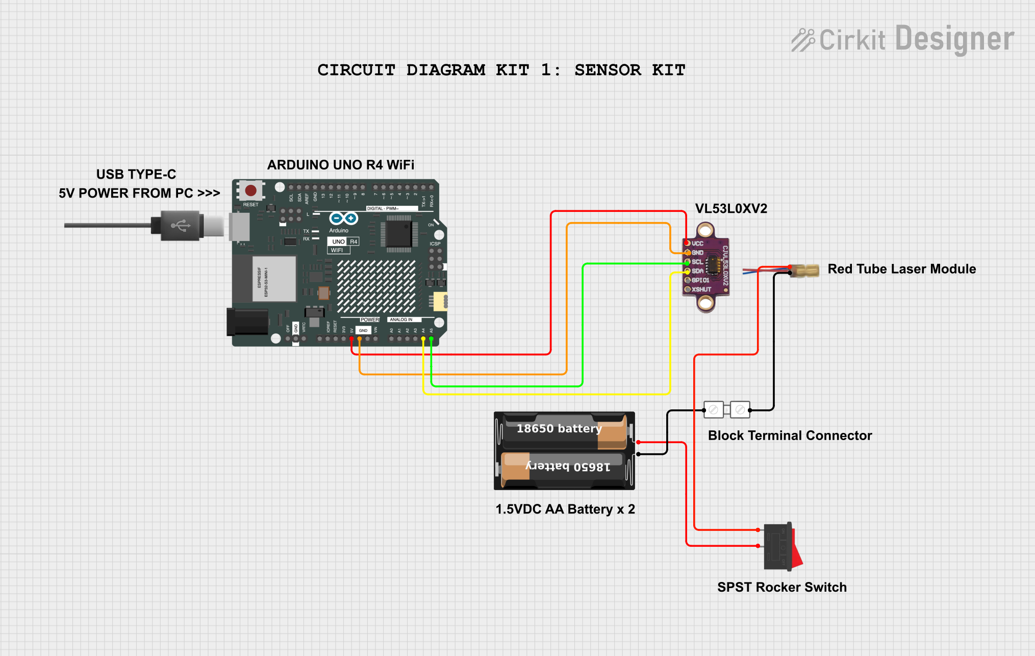
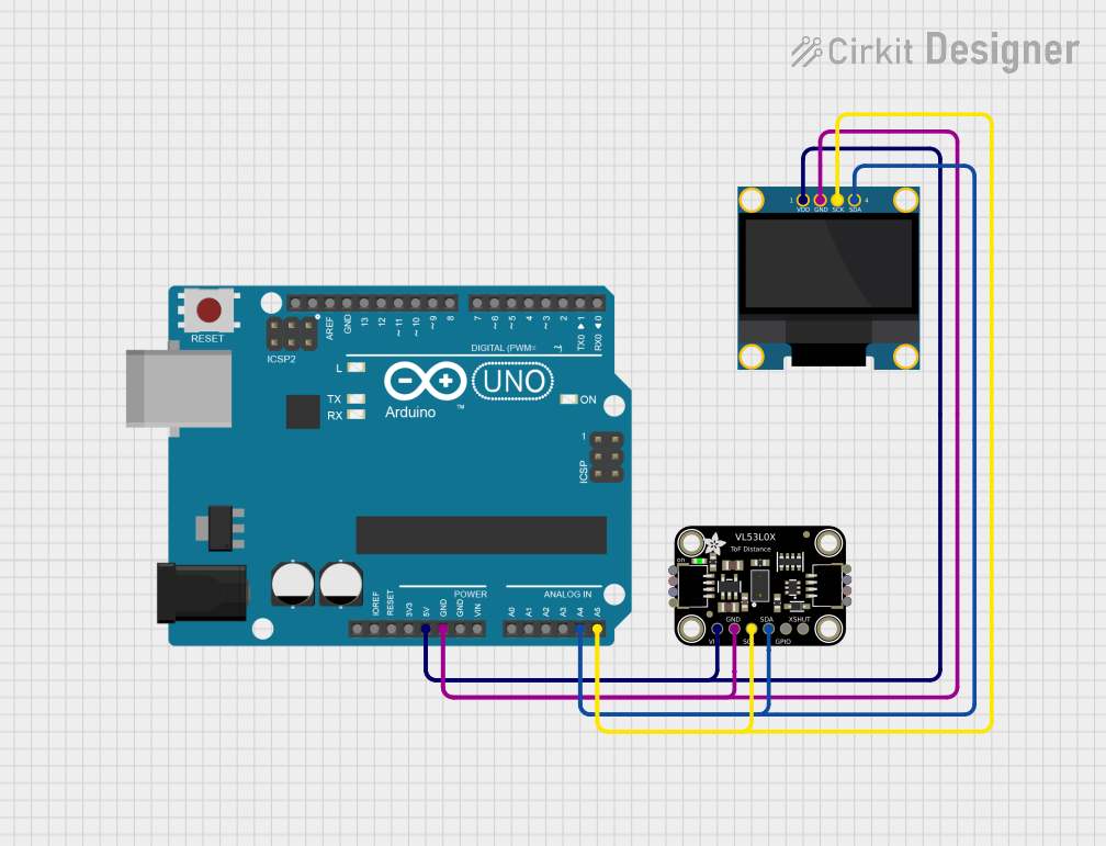
The VL53LOX is straightforward to use in a circuit, especially with microcontrollers like the Arduino UNO. Below are the steps to integrate and use the sensor:
Circuit Connection
- Connect the VIN pin to the 3.3V output of the Arduino UNO.
- Connect the GND pin to the ground (GND) of the Arduino UNO.
- Connect the SDA pin to the A4 pin (I2C data line) of the Arduino UNO.
- Connect the SCL pin to the A5 pin (I2C clock line) of the Arduino UNO.
- Optionally, connect the XSHUT pin to a digital pin on the Arduino for enabling/disabling the sensor.
Arduino Code Example
Below is an example Arduino sketch to read distance data from the VL53LOX using the Wire library:
#include <Wire.h>
#include <Adafruit_VL53L0X.h>

// Create an instance of the VL53L0X sensor
Adafruit_VL53L0X lox = Adafruit_VL53L0X();

void setup() {
  Serial.begin(9600); // Initialize serial communication
  while (!Serial) {
    delay(10); // Wait for the serial port to be ready
  }

  Serial.println("VL53LOX Test");

  // Initialize the sensor
  if (!lox.begin()) {
    Serial.println("Failed to initialize VL53LOX. Check wiring!");
    while (1);
  }
}

void loop() {
  VL53L0X_RangingMeasurementData_t measure;

  // Perform a distance measurement
  lox.rangingTest(&measure, false);

  // Check if the measurement is valid
  if (measure.RangeStatus != 4) { // 4 means out of range
    Serial.print("Distance (mm): ");
    Serial.println(measure.RangeMilliMeter);
  } else {
    Serial.println("Out of range");
  }

  delay(100); // Wait 100ms before the next measurement
}
Important Considerations
- Ensure the sensor is not exposed to direct sunlight or reflective surfaces, as these can interfere with measurements.
- Use pull-up resistors (typically 4.7 kΩ) on the SDA and SCL lines if they are not already present on your board.
- The XSHUT pin can be used to reset the sensor or put it into a low-power state when not in use.
Troubleshooting and FAQs
Common Issues
Sensor not detected by the microcontroller:
- Ensure the I2C connections (SDA and SCL) are correct.
- Verify that the sensor is powered with the correct voltage (2.6 V to 3.5 V).
- Check for proper pull-up resistors on the I2C lines.
Incorrect or fluctuating distance readings:
- Ensure there are no reflective or transparent objects in the sensor's field of view.
- Verify that the sensor is mounted securely and is not vibrating.
Out of range errors:
- Ensure the object is within the sensor's measurement range (30 mm to 2 m).
- Avoid using the sensor in extremely bright environments.
FAQs
Q: Can the VL53LOX measure distances beyond 2 meters?
A: No, the maximum range of the VL53LOX is 2 meters. For longer ranges, consider other ToF sensors.
Q: Can I use the VL53LOX with a 5V microcontroller?
A: Yes, but you will need a logic level shifter to safely interface the 3.3V I2C lines with the 5V microcontroller.
Q: How can I reduce power consumption?
A: Use the XSHUT pin to put the sensor into a low-power state when not in use.
Q: Is the VL53LOX affected by ambient light?
A: While the sensor is designed to work in various lighting conditions, excessive ambient light or direct sunlight can reduce accuracy.