How to Use MAX3421E: Examples, Pinouts, and Specs
Introduction
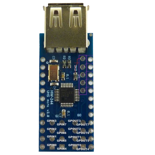
The MAX3421E is a USB peripheral controller manufactured by Analog Devices / Maxim Integrated. It enables microcontrollers to communicate with USB devices by providing a full-speed USB interface. The MAX3421E supports various USB protocols, including control, bulk, interrupt, and isochronous transfers, making it a versatile solution for USB connectivity in embedded systems.
Explore Projects Built with MAX3421E
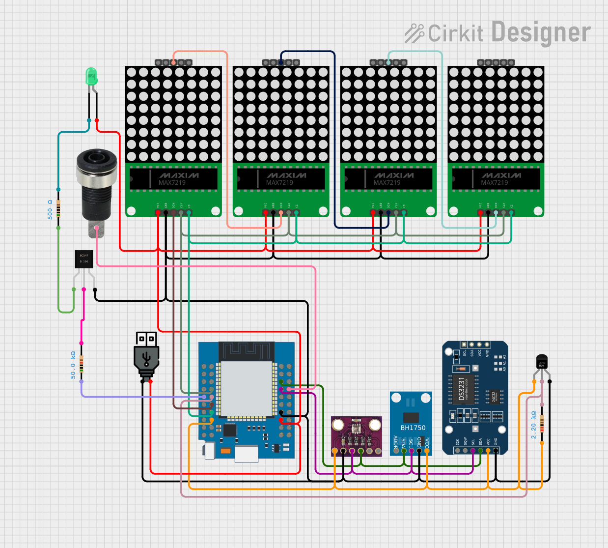
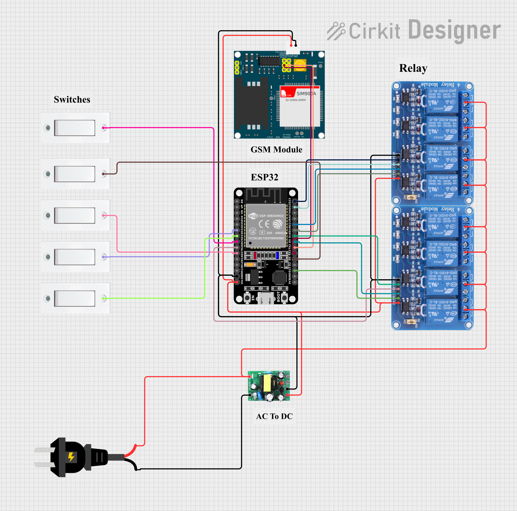


Explore Projects Built with MAX3421E
Common Applications and Use Cases
- USB host controllers for embedded systems
- USB device communication in microcontroller-based designs
- USB protocol analyzers
- Industrial and consumer electronics requiring USB connectivity
- USB-to-serial converters
Technical Specifications
Key Technical Details
- Manufacturer Part IDs: MAX3421EETJ+, MAX3421EEHJ+
- USB Interface: Full-speed (12 Mbps) USB host or peripheral controller
- Operating Voltage: 3.0V to 3.6V (core), 4.0V to 5.5V (USB transceiver)
- Current Consumption: 15 mA (typical, active mode)
- Operating Temperature Range: -40°C to +85°C
- Package Options:
- MAX3421EETJ+: 32-pin TQFP
- MAX3421EEHJ+: 32-pin TQFN
- Communication Interface: SPI (Serial Peripheral Interface)
- Integrated Features:
- USB transceiver
- Internal clock oscillator
- 3.3V regulator for USB signaling
- Interrupt output for event signaling
- ESD Protection: ±15kV (human body model)
Pin Configuration and Descriptions
MAX3421E Pinout (32-pin TQFP/TQFN)
| Pin | Name | Type | Description |
|---|---|---|---|
| 1 | VCC | Power | 3.3V core power supply. |
| 2 | GND | Ground | Ground connection. |
| 3 | MOSI | Input | SPI Master Out Slave In (data input to MAX3421E). |
| 4 | MISO | Output | SPI Master In Slave Out (data output from MAX3421E). |
| 5 | SCK | Input | SPI clock input. |
| 6 | SS | Input | SPI slave select (active low). |
| 7 | INT | Output | Interrupt output (active low). Signals USB or SPI events. |
| 8 | RESET | Input | Active-low reset input. |
| 9 | D+ | I/O | USB D+ line for differential signaling. |
| 10 | D- | I/O | USB D- line for differential signaling. |
| 11 | VBUS | Power | USB bus power input (4.0V to 5.5V). |
| 12 | GND | Ground | Ground connection for USB transceiver. |
| 13-32 | NC/Other Pins | - | Reserved or no connection (refer to the datasheet for detailed pin functions). |
Usage Instructions
How to Use the MAX3421E in a Circuit
- Power Supply: Connect the VCC pin to a 3.3V regulated power source and the VBUS pin to a 5V USB power source. Ensure proper decoupling capacitors are placed near the power pins.
- SPI Communication: Connect the SPI pins (MOSI, MISO, SCK, SS) to the corresponding SPI pins of the microcontroller. Configure the SPI interface for mode 0 (CPOL=0, CPHA=0).
- USB Connection: Connect the D+ and D- pins to the USB device or host. Use proper termination resistors as specified in the datasheet.
- Interrupt Handling: Connect the INT pin to a GPIO pin on the microcontroller to handle USB or SPI events.
- Reset: Use the RESET pin to initialize the MAX3421E during power-up or when required.
Important Considerations and Best Practices
- Voltage Levels: Ensure the SPI signals are compatible with the MAX3421E's 3.3V logic levels.
- ESD Protection: Use external ESD protection diodes if the device is exposed to harsh environments.
- Clock Source: The MAX3421E has an internal oscillator, but an external crystal (12 MHz) can be used for better timing accuracy.
- Firmware: Use a USB stack or library compatible with the MAX3421E to simplify development.
Example: Connecting MAX3421E to Arduino UNO
The MAX3421E can be used with an Arduino UNO to create a USB host controller. Below is an example of initializing the MAX3421E using the popular USB Host Shield library.
Arduino Code Example
#include <Usb.h> // Include USB Host Shield library
#include <usbhub.h> // Include USB hub support

USB Usb; // Create USB object
USBHub Hub(&Usb); // Create USB hub object

void setup() {
  Serial.begin(9600); // Initialize serial communication
  if (Usb.Init() == -1) {
    // If USB initialization fails, print an error message
    Serial.println("USB initialization failed. Check connections.");
    while (1); // Halt execution
  }
  Serial.println("USB initialized successfully.");
}

void loop() {
  Usb.Task(); // Handle USB tasks
  // Add your USB device handling code here
}
Notes:
- Install the USB Host Shield library in the Arduino IDE before running the code.
- Ensure proper wiring between the Arduino UNO and the MAX3421E SPI pins.
Troubleshooting and FAQs
Common Issues and Solutions
USB Initialization Fails:
- Cause: Incorrect SPI connections or power supply issues.
- Solution: Verify SPI wiring and ensure the VCC and VBUS pins are powered correctly.
No Response from USB Device:
- Cause: Improper USB connection or unsupported device.
- Solution: Check the D+ and D- connections and ensure the device is compatible with the MAX3421E.
Interrupts Not Triggering:
- Cause: INT pin not connected or microcontroller not configured to handle interrupts.
- Solution: Verify the INT pin connection and configure the microcontroller to detect falling edges.
Overheating:
- Cause: Excessive current draw or incorrect power supply voltage.
- Solution: Ensure the power supply voltage is within the specified range and check for short circuits.
FAQs
Q: Can the MAX3421E act as both a USB host and device?
A: Yes, the MAX3421E can function as either a USB host or peripheral, depending on the configuration.Q: What is the maximum USB speed supported?
A: The MAX3421E supports full-speed USB (12 Mbps).Q: Is the MAX3421E compatible with 5V logic microcontrollers?
A: No, the MAX3421E operates at 3.3V logic levels. Use level shifters if interfacing with 5V logic.Q: Does the MAX3421E require an external crystal?
A: No, it has an internal oscillator, but an external 12 MHz crystal can be used for better accuracy.