How to Use SSD1306 128x64 SPI OLED: Examples, Pinouts, and Specs
Introduction
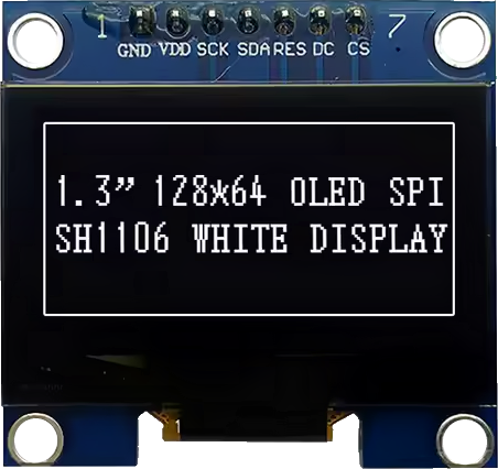
The SSD1306 128x64 SPI OLED display module, manufactured by Solomon Systech (Part ID: SSD1306 SPI), is a monochrome display with a resolution of 128x64 pixels. This module is widely used in embedded systems for displaying text, graphics, and simple animations. Its compact size and low power consumption make it ideal for a variety of applications, including wearable devices, instrumentation, and portable electronics.
Explore Projects Built with SSD1306 128x64 SPI OLED

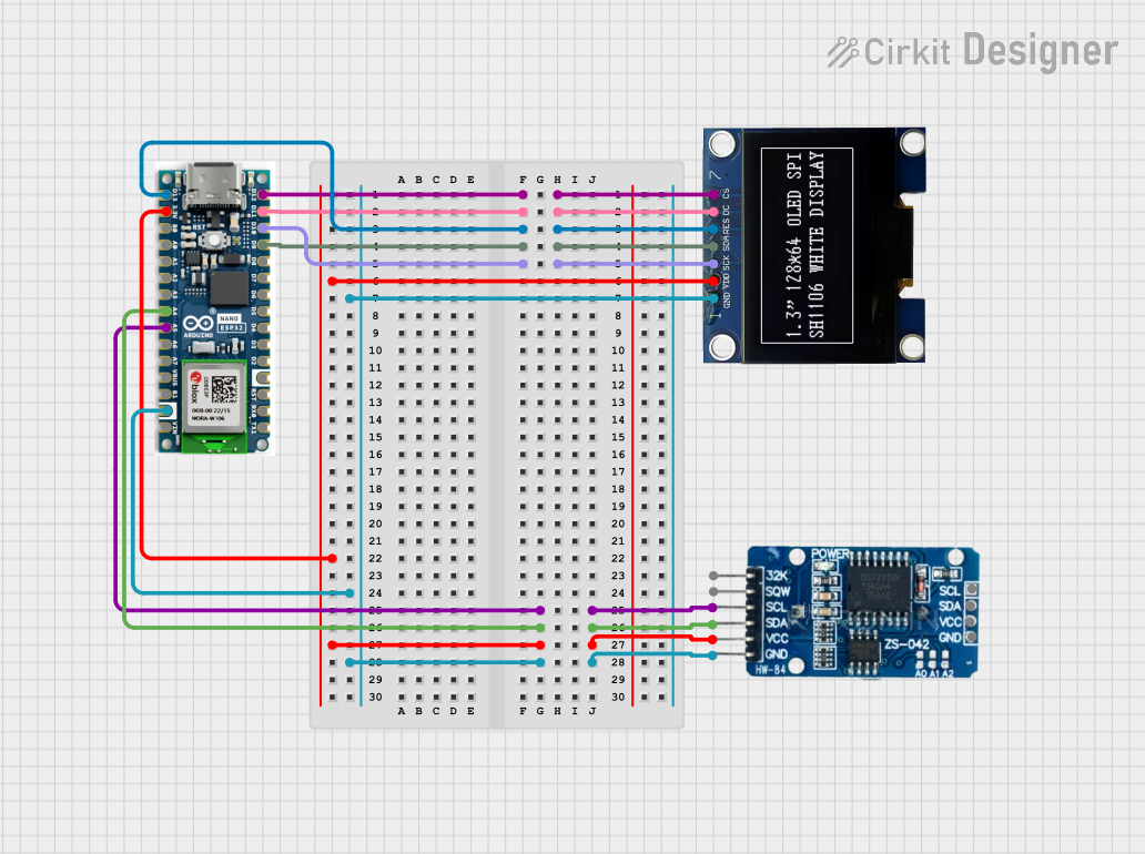
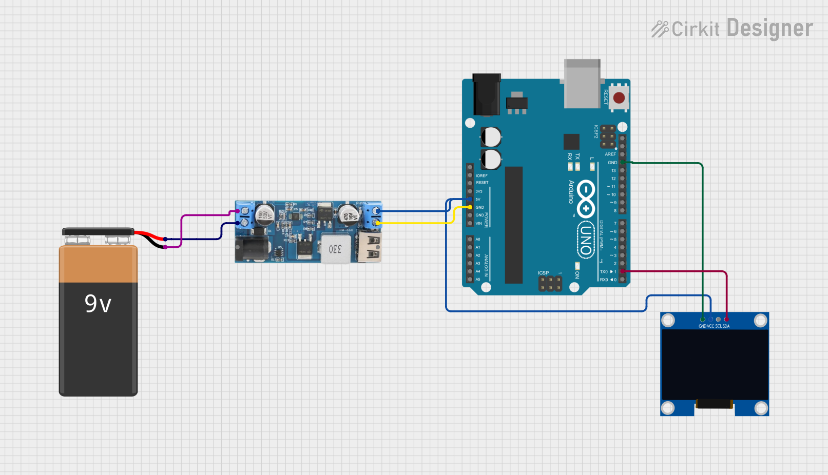
Explore Projects Built with SSD1306 128x64 SPI OLED
Technical Specifications
Key Technical Details
| Parameter | Value |
|---|---|
| Display Type | OLED |
| Resolution | 128x64 pixels |
| Driver IC | SSD1306 |
| Interface | SPI |
| Operating Voltage | 3.3V - 5V |
| Operating Current | 20mA (typical) |
| Viewing Angle | >160° |
| Operating Temperature | -40°C to 85°C |
Pin Configuration and Descriptions
| Pin No. | Pin Name | Description |
|---|---|---|
| 1 | GND | Ground |
| 2 | VCC | Power Supply (3.3V - 5V) |
| 3 | D0 (SCK) | Serial Clock (SPI Clock) |
| 4 | D1 (MOSI) | Serial Data (SPI Data) |
| 5 | RES | Reset |
| 6 | DC | Data/Command Control |
| 7 | CS | Chip Select |
Usage Instructions
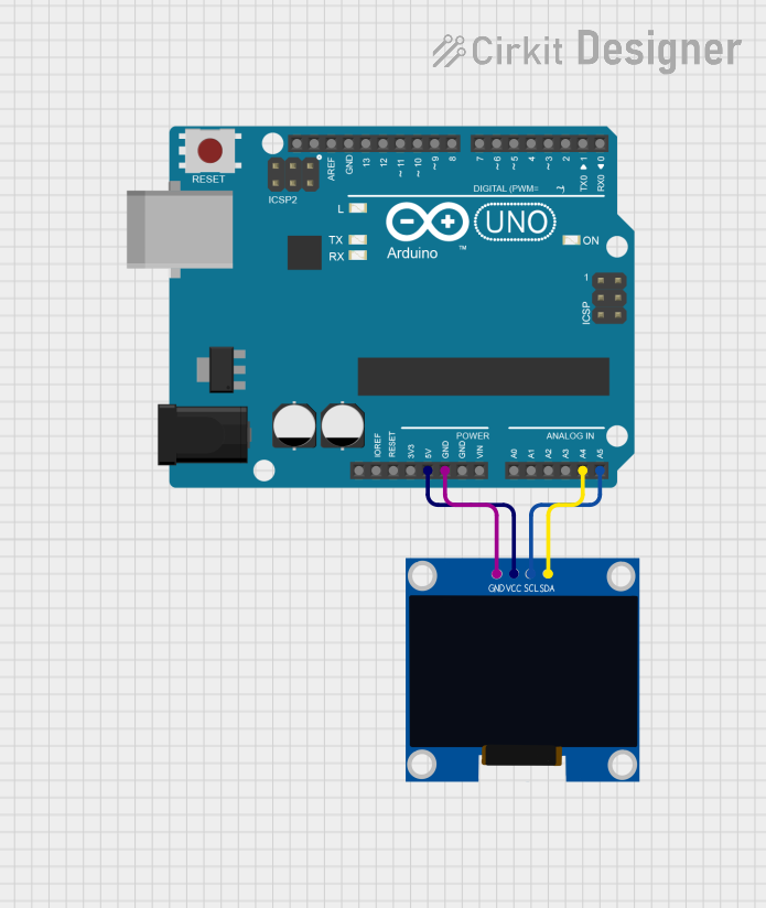
Connecting the SSD1306 to an Arduino UNO
To use the SSD1306 128x64 SPI OLED display with an Arduino UNO, follow these steps:
Wiring:
- Connect the GND pin of the display to the GND pin of the Arduino.
- Connect the VCC pin of the display to the 5V pin of the Arduino.
- Connect the D0 (SCK) pin of the display to the pin 13 of the Arduino.
- Connect the D1 (MOSI) pin of the display to the pin 11 of the Arduino.
- Connect the RES pin of the display to the pin 8 of the Arduino.
- Connect the DC pin of the display to the pin 9 of the Arduino.
- Connect the CS pin of the display to the pin 10 of the Arduino.
Library Installation:
- Install the
Adafruit SSD1306andAdafruit GFXlibraries from the Arduino Library Manager.
- Install the
Example Code:
#include <SPI.h>
#include <Wire.h>
#include <Adafruit_GFX.h>
#include <Adafruit_SSD1306.h>

// Define OLED display width and height
#define SCREEN_WIDTH 128
#define SCREEN_HEIGHT 64

// Define the reset pin
#define OLED_RESET 8

// Create an instance of the SSD1306 display
Adafruit_SSD1306 display(SCREEN_WIDTH, SCREEN_HEIGHT, &SPI, OLED_RESET, 9, 10);

void setup() {
  // Initialize the display
  if(!display.begin(SSD1306_SWITCHCAPVCC, 0x3C)) {
    Serial.println(F("SSD1306 allocation failed"));
    for(;;);
  }
  display.display();
  delay(2000); // Pause for 2 seconds

  // Clear the buffer
  display.clearDisplay();

  // Display text
  display.setTextSize(1);      // Normal 1:1 pixel scale
  display.setTextColor(SSD1306_WHITE); // Draw white text
  display.setCursor(0, 0);     // Start at top-left corner
  display.println(F("Hello, world!"));
  display.display();
}

void loop() {
  // Add your main code here, to run repeatedly
}
Important Considerations and Best Practices
- Power Supply: Ensure that the power supply voltage is within the specified range (3.3V - 5V) to avoid damaging the display.
- Reset Pin: The RES pin should be properly connected to ensure the display initializes correctly.
- Data/Command Control: The DC pin is crucial for distinguishing between data and command signals. Ensure it is correctly wired.
- Library Compatibility: Use the recommended libraries (
Adafruit SSD1306andAdafruit GFX) for seamless integration and functionality.
Troubleshooting and FAQs
Common Issues and Solutions
Display Not Turning On:
- Solution: Check the power connections and ensure the VCC and GND pins are properly connected.
Garbage Display or No Display:
- Solution: Verify the wiring, especially the SPI connections (D0, D1, CS, DC, RES). Ensure the correct pins are used.
Library Initialization Failure:
- Solution: Ensure the
Adafruit SSD1306andAdafruit GFXlibraries are correctly installed. Check the I2C address in thedisplay.begin()function.
- Solution: Ensure the
FAQs
Can I use the SSD1306 display with other microcontrollers?
- Yes, the SSD1306 display can be used with various microcontrollers, including ESP8266, ESP32, and STM32, with appropriate libraries and wiring.
What is the maximum SPI clock speed supported by the SSD1306?
- The SSD1306 supports SPI clock speeds up to 10 MHz.
Can I use the SSD1306 display in low-temperature environments?
- Yes, the SSD1306 display operates within a temperature range of -40°C to 85°C, making it suitable for low-temperature environments.
By following this documentation, users can effectively integrate and utilize the SSD1306 128x64 SPI OLED display module in their projects, ensuring optimal performance and reliability.