How to Use 4S40A BMS: Examples, Pinouts, and Specs
Introduction
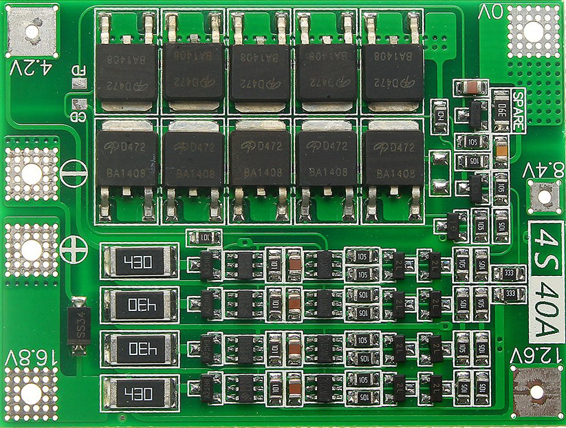
The 4S40A Battery Management System (BMS) is a crucial component designed for 4-cell lithium-ion battery packs. It is capable of handling up to 40 amps of current, ensuring the safe operation of the battery pack by monitoring and balancing the cells. The BMS protects against overcharge, over-discharge, and short circuits, making it an essential component for maintaining the longevity and safety of lithium-ion batteries.
Explore Projects Built with 4S40A BMS


Explore Projects Built with 4S40A BMS
Common Applications and Use Cases
- Electric Vehicles (EVs): Ensures the safe operation of battery packs in electric cars, bikes, and scooters.
- Renewable Energy Systems: Manages battery packs in solar and wind energy storage systems.
- Portable Electronics: Used in high-capacity power banks and portable electronic devices.
- Uninterruptible Power Supplies (UPS): Ensures reliable power backup by managing battery health.
Technical Specifications
Key Technical Details
| Parameter | Value |
|---|---|
| Battery Configuration | 4-cell (4S) |
| Maximum Current | 40A |
| Overcharge Protection | 4.25V ± 0.05V per cell |
| Over-discharge Protection | 2.8V ± 0.05V per cell |
| Balance Current | 60mA |
| Operating Temperature | -20°C to 60°C |
| Storage Temperature | -40°C to 80°C |
Pin Configuration and Descriptions
| Pin Number | Pin Name | Description |
|---|---|---|
| 1 | B+ | Battery positive terminal |
| 2 | B- | Battery negative terminal |
| 3 | P+ | Power output positive terminal |
| 4 | P- | Power output negative terminal |
| 5 | C- | Charging negative terminal |
| 6 | B1 | Connection to the positive terminal of cell 1 |
| 7 | B2 | Connection to the positive terminal of cell 2 |
| 8 | B3 | Connection to the positive terminal of cell 3 |
| 9 | B4 | Connection to the positive terminal of cell 4 |
Usage Instructions
How to Use the Component in a Circuit
Connect the Battery Pack:
- Connect the positive terminal of the battery pack to the B+ pin.
- Connect the negative terminal of the battery pack to the B- pin.
- Connect the individual cell terminals to B1, B2, B3, and B4 respectively.
Connect the Load:
- Connect the positive terminal of the load to the P+ pin.
- Connect the negative terminal of the load to the P- pin.
Connect the Charger:
- Connect the positive terminal of the charger to the B+ pin.
- Connect the negative terminal of the charger to the C- pin.
Important Considerations and Best Practices
- Ensure Proper Connections: Double-check all connections to avoid short circuits and ensure proper operation.
- Use Appropriate Wire Gauges: Use wires that can handle the maximum current (40A) to prevent overheating.
- Monitor Temperature: Ensure the BMS operates within the specified temperature range to avoid damage.
- Balance Cells Regularly: Regularly balance the cells to maintain battery health and performance.
Troubleshooting and FAQs
Common Issues and Solutions
Issue: BMS Not Balancing Cells
- Solution: Ensure all cell connections (B1, B2, B3, B4) are secure and properly connected.
Issue: Overcharge/Over-discharge Protection Triggering Frequently
- Solution: Check the individual cell voltages. Replace any faulty cells that are not holding charge properly.
Issue: BMS Overheating
- Solution: Ensure proper ventilation and use appropriate wire gauges. Check for any short circuits.
FAQs
Q1: Can I use the 4S40A BMS with a different battery configuration?
- A1: No, the 4S40A BMS is specifically designed for 4-cell (4S) lithium-ion battery packs.
Q2: How do I know if the BMS is balancing the cells?
- A2: You can measure the voltage of each cell. If the voltages are close to each other, the BMS is balancing the cells.
Q3: Can I use the BMS with an Arduino UNO for monitoring?
- A3: Yes, you can use the BMS with an Arduino UNO to monitor cell voltages and overall battery health. Below is an example code snippet for monitoring cell voltages using an Arduino UNO:
// Example code to monitor cell voltages using Arduino UNO

const int cell1Pin = A0; // Analog pin for cell 1
const int cell2Pin = A1; // Analog pin for cell 2
const int cell3Pin = A2; // Analog pin for cell 3
const int cell4Pin = A3; // Analog pin for cell 4

void setup() {
  Serial.begin(9600); // Initialize serial communication
}

void loop() {
  float cell1Voltage = analogRead(cell1Pin) * (5.0 / 1023.0) * 2; // Read and convert voltage
  float cell2Voltage = analogRead(cell2Pin) * (5.0 / 1023.0) * 2; // Read and convert voltage
  float cell3Voltage = analogRead(cell3Pin) * (5.0 / 1023.0) * 2; // Read and convert voltage
  float cell4Voltage = analogRead(cell4Pin) * (5.0 / 1023.0) * 2; // Read and convert voltage

  Serial.print("Cell 1 Voltage: ");
  Serial.println(cell1Voltage);
  Serial.print("Cell 2 Voltage: ");
  Serial.println(cell2Voltage);
  Serial.print("Cell 3 Voltage: ");
  Serial.println(cell3Voltage);
  Serial.print("Cell 4 Voltage: ");
  Serial.println(cell4Voltage);

  delay(1000); // Wait for 1 second before next reading
}
This code reads the voltages of the four cells and prints them to the serial monitor. Ensure you have the appropriate voltage dividers if the cell voltages exceed the Arduino's analog input range.
This documentation provides a comprehensive guide to understanding, using, and troubleshooting the 4S40A BMS. Whether you are a beginner or an experienced user, this guide aims to help you make the most of your BMS for safe and efficient battery management.