How to Use ESP 01 Adapter: Examples, Pinouts, and Specs
Introduction
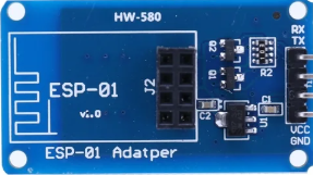
The ESP 01 Adapter (Manufacturer Part ID: HW-580) is a compact adapter board designed to interface with the ESP8266 ESP-01 Wi-Fi module. It simplifies the process of connecting the ESP-01 module to other devices by providing the necessary power regulation, pin connections, and communication interfaces. This adapter is particularly useful for prototyping and integrating the ESP-01 module into IoT projects.
Explore Projects Built with ESP 01 Adapter


Explore Projects Built with ESP 01 Adapter
Common Applications and Use Cases
- IoT Projects: Enables seamless integration of the ESP-01 module for Wi-Fi connectivity.
- Prototyping: Simplifies the connection of the ESP-01 to breadboards or microcontrollers.
- Programming: Provides an easy way to program the ESP-01 module using USB-to-serial converters.
- Power Regulation: Converts 5V input to the 3.3V required by the ESP-01 module.
Technical Specifications
The ESP 01 Adapter is designed to work specifically with the ESP-01 Wi-Fi module. Below are its key technical details:
Key Technical Details
- Input Voltage: 5V DC (via VCC pin or USB power source)
- Output Voltage: 3.3V DC (regulated for the ESP-01 module)
- Current Rating: Up to 500mA
- Dimensions: 25mm x 15mm x 10mm (approx.)
- Communication Interface: UART (TX, RX pins)
- Power Regulation: Onboard AMS1117 3.3V voltage regulator
- LED Indicators: Power and communication status LEDs
Pin Configuration and Descriptions
The ESP 01 Adapter has a simple pinout designed to match the ESP-01 module. Below is the pin configuration:
| Pin Name | Description |
|---|---|
| VCC | 5V input power pin. Provides power to the onboard voltage regulator. |
| GND | Ground connection. |
| TX | UART Transmit pin. Connects to the RX pin of the microcontroller or USB-TTL. |
| RX | UART Receive pin. Connects to the TX pin of the microcontroller or USB-TTL. |
| CH_PD | Chip Enable pin. Must be connected to 3.3V for the ESP-01 to function. |
| GPIO0 | General-purpose I/O pin. Used for programming or other custom functions. |
| GPIO2 | General-purpose I/O pin. |
| RST | Reset pin. Pull low to reset the ESP-01 module. |
Usage Instructions
The ESP 01 Adapter is straightforward to use and is designed to simplify the connection of the ESP-01 module. Follow the steps below to use it effectively:
Connecting the ESP-01 Module
- Insert the ESP-01 Module: Align the pins of the ESP-01 module with the adapter's socket and gently insert it.
- Power the Adapter: Provide a 5V DC input to the VCC pin or connect a USB-to-serial converter to power the adapter.
- Connect to a Microcontroller:
- Connect the TX pin of the adapter to the RX pin of the microcontroller.
- Connect the RX pin of the adapter to the TX pin of the microcontroller.
- Connect the GND pin of the adapter to the GND pin of the microcontroller.
Programming the ESP-01 Module
To program the ESP-01 module using the adapter:
- Connect the adapter to a USB-to-serial converter.
- Pull the GPIO0 pin low (connect it to GND) to enter programming mode.
- Use an IDE like Arduino IDE to upload the code to the ESP-01 module.
Example Code for Arduino UNO
Below is an example of how to use the ESP-01 module with an Arduino UNO to connect to a Wi-Fi network:
#include <SoftwareSerial.h>

// Define RX and TX pins for SoftwareSerial
SoftwareSerial espSerial(2, 3); // RX = Pin 2, TX = Pin 3

void setup() {
  Serial.begin(9600); // Start Serial Monitor at 9600 baud
  espSerial.begin(9600); // Start ESP-01 communication at 9600 baud

  Serial.println("Initializing ESP-01...");
  espSerial.println("AT"); // Send AT command to check communication

  delay(1000); // Wait for response
  while (espSerial.available()) {
    Serial.write(espSerial.read()); // Print ESP-01 response to Serial Monitor
  }

  // Connect to Wi-Fi
  espSerial.println("AT+CWJAP=\"YourSSID\",\"YourPassword\""); // Replace with your Wi-Fi credentials
  delay(5000); // Wait for connection
  while (espSerial.available()) {
    Serial.write(espSerial.read()); // Print connection response
  }
}

void loop() {
  // Add your main code here
}
Important Considerations and Best Practices
- Ensure the CH_PD pin is connected to 3.3V for the ESP-01 module to function.
- Do not power the ESP-01 module directly with 5V; always use the adapter's regulated 3.3V output.
- Use a level shifter or voltage divider for the RX pin if connecting to a 5V microcontroller.
- Avoid inserting or removing the ESP-01 module while the adapter is powered.
Troubleshooting and FAQs
Common Issues and Solutions
ESP-01 Module Not Responding:
- Ensure the CH_PD pin is connected to 3.3V.
- Verify the connections between the adapter and the microcontroller or USB-to-serial converter.
- Check the baud rate in your code or serial monitor (default is 9600).
Programming Fails:
- Ensure the GPIO0 pin is pulled low before uploading code.
- Verify that the USB-to-serial converter is properly connected and recognized by your computer.
Wi-Fi Connection Fails:
- Double-check the SSID and password in your code.
- Ensure the Wi-Fi network is within range and supports 2.4GHz (ESP-01 does not support 5GHz).
FAQs
Can I use the ESP 01 Adapter with other ESP modules? No, the adapter is specifically designed for the ESP-01 module and may not be compatible with other ESP modules.
What is the maximum input voltage for the adapter? The adapter can accept a maximum input voltage of 5V DC.
Do I need additional components to use the adapter? No, the adapter includes an onboard voltage regulator and is ready to use with the ESP-01 module.
By following this documentation, you can effectively use the ESP 01 Adapter to simplify your ESP-01 module projects.