The DC/DC TSR 3N Serie 15 W, 5 VDC, 3A is a compact, high-efficiency DC-DC converter manufactured by Traco. It is designed to provide a regulated 5 VDC output with a maximum current of 3A, making it ideal for powering a wide range of electronic devices. This component is a drop-in replacement for traditional linear regulators, offering improved efficiency and reduced heat dissipation.
Explore Projects Built with DC/DC TSR 3N Serie 15 W, 5 VDC, 3A
Use Cirkit Designer to design, explore, and prototype these projects online. Some projects support real-time simulation. Click "Open Project" to start designing instantly!
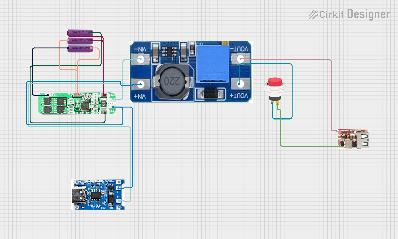
This circuit is a battery management and power supply system that uses three 3.7V batteries connected to a 3S 10A Li-ion 18650 Charger Protection Board Module for balanced charging and protection. The system includes a TP4056 Battery Charging Protection Module for additional charging safety, a Step Up Boost Power Converter to regulate and boost the voltage, and a USB regulator to provide a stable 5V output, controlled by a push switch.
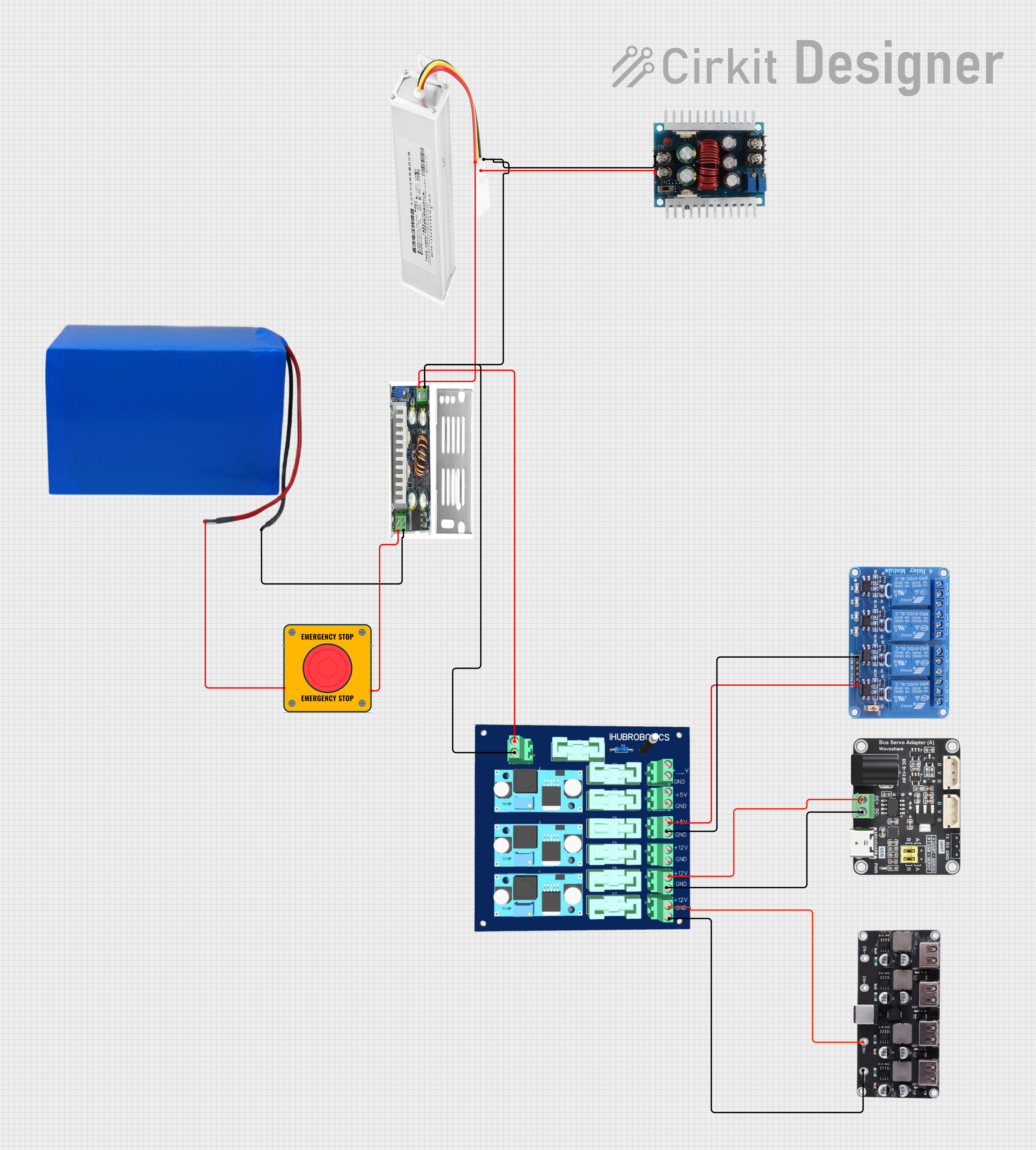
This circuit converts a 38.5V battery output to multiple lower voltage levels using a series of DC-DC converters and a power module. It includes an emergency stop switch for safety and distributes power to various components such as a relay module, USB ports, and a bus servo adaptor.
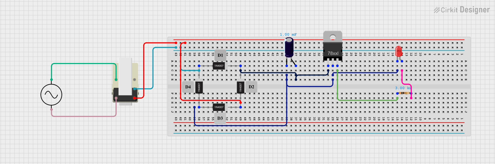
This circuit is a basic AC to DC power supply with voltage regulation. It includes a transformer to step down the AC voltage, a bridge rectifier made of 1N4007 diodes to convert AC to DC, an electrolytic capacitor for smoothing, and a voltage regulator to provide a stable DC output. An LED with a current-limiting resistor indicates the presence of the output voltage.
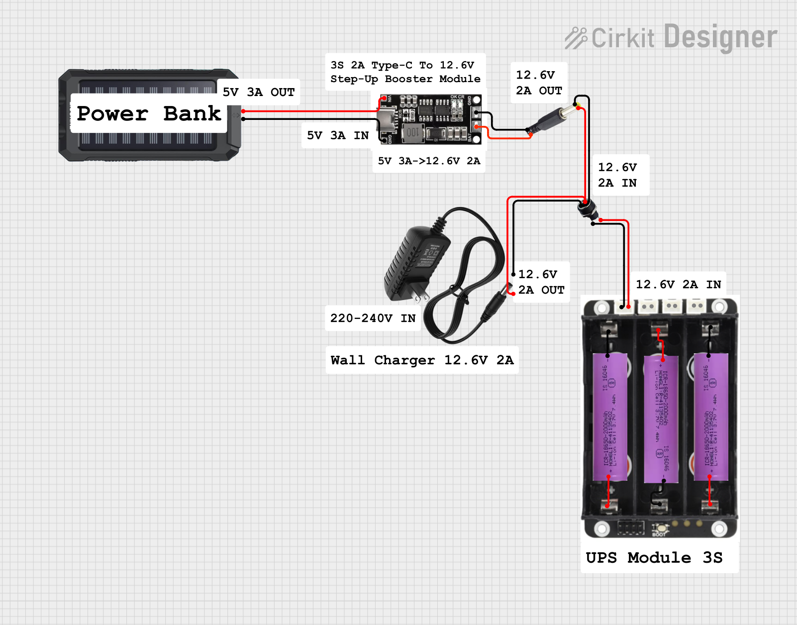
This circuit is a power management system that integrates a 12V power supply, a solar charger power bank, and multiple Li-ion batteries to provide a stable power output. The Waveshare UPS 3S manages the input from the power sources and batteries, ensuring continuous power delivery. The MRB045 module is used to interface the solar charger with the rest of the system.
Powering microcontrollers, sensors, and other low-voltage devices
Replacing linear voltage regulators in circuits to improve efficiency
Battery-powered applications where energy efficiency is critical
Industrial automation and control systems
Consumer electronics and portable devices
Technical Specifications
The following table outlines the key technical details of the TSR 3N Serie:
Parameter
Value
Input Voltage Range
6.5 VDC to 36 VDC
Output Voltage
5 VDC
Maximum Output Current
3A
Output Power
15 W
Efficiency
Up to 96%
Operating Temperature
-40°C to +85°C
Package Type
SIP-3 (Single Inline Package)
Dimensions
11.5 x 8.5 x 17.5 mm
Weight
4.5 g
Pin Configuration and Descriptions
The TSR 3N Serie features a simple 3-pin configuration, as shown below:
Pin Number
Pin Name
Description
1
Input (VIN)
Connect to the positive input voltage.
2
Ground (GND)
Connect to the circuit ground.
3
Output (VOUT)
Provides the regulated 5 VDC output.
Usage Instructions
How to Use the Component in a Circuit
Input Voltage Connection: Connect the input voltage (6.5 VDC to 36 VDC) to the VIN pin. Ensure the input voltage is within the specified range to avoid damage to the component.
Ground Connection: Connect the GND pin to the circuit ground.
Output Voltage Connection: Connect the VOUT pin to the load that requires a regulated 5 VDC supply.
Bypass Capacitors: For optimal performance, place a low-ESR capacitor (e.g., 10 µF) across the input and output pins to reduce noise and improve stability.
Important Considerations and Best Practices
Thermal Management: Although the TSR 3N Serie is highly efficient, ensure adequate ventilation or heat dissipation in high-current applications.
Input Voltage Range: Always verify that the input voltage remains within the specified range (6.5 VDC to 36 VDC).
Load Requirements: Ensure the connected load does not exceed the maximum output current of 3A.
Polarity Protection: Use a diode or other protection mechanism to prevent damage from reverse polarity connections.
Example: Using with an Arduino UNO
The TSR 3N Serie can be used to power an Arduino UNO by providing a stable 5 VDC supply. Below is an example circuit and code:
Circuit Connection
Connect the VIN pin of the TSR 3N to a 12 VDC power source.
Connect the GND pin of the TSR 3N to the ground of the power source and the Arduino UNO.
Connect the VOUT pin of the TSR 3N to the 5V pin of the Arduino UNO.
Arduino Code Example
// Example code to blink an LED using Arduino UNO powered by TSR 3N
// Ensure the TSR 3N provides a stable 5V supply to the Arduino UNO.

const int ledPin = 13; // Built-in LED pin on Arduino UNO

void setup() {
  pinMode(ledPin, OUTPUT); // Set the LED pin as an output
}

void loop() {
  digitalWrite(ledPin, HIGH); // Turn the LED on
  delay(1000);                // Wait for 1 second
  digitalWrite(ledPin, LOW);  // Turn the LED off
  delay(1000);                // Wait for 1 second
}
Troubleshooting and FAQs
Common Issues and Solutions
No Output Voltage:
Verify that the input voltage is within the specified range (6.5 VDC to 36 VDC).
Check for proper connections to the VIN, GND, and VOUT pins.
Ensure the load does not exceed the maximum output current of 3A.
Overheating:
Ensure adequate ventilation or heat dissipation in the circuit.
Check for excessive load current or input voltage near the upper limit.
Output Voltage Instability:
Add low-ESR capacitors (e.g., 10 µF) across the input and output pins.
Verify that the input voltage is stable and free from significant noise.
FAQs
Q: Can the TSR 3N Serie be used with a battery as the input source?
A: Yes, the TSR 3N Serie can be powered by a battery, provided the battery voltage is within the input range of 6.5 VDC to 36 VDC.
Q: Is the TSR 3N Serie protected against reverse polarity?
A: No, the TSR 3N Serie does not have built-in reverse polarity protection. It is recommended to use an external diode for protection.
Q: Can I use the TSR 3N Serie to power multiple devices simultaneously?
A: Yes, as long as the total current draw of all devices does not exceed 3A.
Q: Does the TSR 3N Serie require a heatsink?
A: In most cases, a heatsink is not required due to its high efficiency. However, in high-current applications, ensure proper ventilation to prevent overheating.


 Open Project in Cirkit Designer