Cirkit Designer Logo
Cirkit Designer
Your all-in-one circuit design IDE
Home / 
Component Documentation

How to Use Battery Switch ON/OFF 275A: Examples, Pinouts, and Specs

Image of Battery Switch ON/OFF 275A
Cirkit Designer LogoDesign with Battery Switch ON/OFF 275A in Cirkit Designer

Introduction

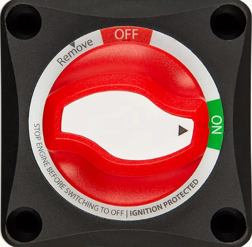
The Battery Switch ON/OFF 275A is a heavy-duty switch designed to connect or disconnect a battery from a circuit. With a current handling capacity of up to 275 amps, this switch is ideal for high-power applications. It is commonly used in automotive, marine, and industrial systems to ensure safety, prevent battery drain, and provide control over the power supply. Its robust design makes it suitable for harsh environments, offering reliable performance in demanding conditions.

Explore Projects Built with Battery Switch ON/OFF 275A

Use Cirkit Designer to design, explore, and prototype these projects online. Some projects support real-time simulation. Click "Open Project" to start designing instantly!
12V UPS System with Dual 18650 Li-ion Battery Backup and Voltage Regulation
Image of Power supply: A project utilizing Battery Switch ON/OFF 275A in a practical application
This circuit is designed to provide an uninterruptible power supply (UPS) system with a 12V DC output. It includes a 12V 5A power supply connected to an AC source through a toggle switch, which charges a pair of 18650 Li-ion batteries via a voltage regulator (XL4016). The UPS module ensures a continuous power supply to the load by switching between the power supply and the battery bank.
Cirkit Designer LogoOpen Project in Cirkit Designer
Battery-Powered UPS with Step-Down Buck Converter and BMS
Image of Mini ups: A project utilizing Battery Switch ON/OFF 275A in a practical application
This circuit is a power management system that steps down a 240V AC input to a lower DC voltage using a buck converter, which then powers a 40W UPS. The UPS is controlled by a rocker switch and is backed up by a battery management system (BMS) connected to three 3.7V batteries in series, ensuring continuous power supply.
Cirkit Designer LogoOpen Project in Cirkit Designer
Battery-Powered Adjustable Voltage Regulator with Li-ion 18650 Batteries and BMS
Image of mini ups: A project utilizing Battery Switch ON/OFF 275A in a practical application
This circuit is a power management system that uses four Li-ion 18650 batteries connected to a 2S 30A BMS for battery management and protection. The system includes step-up and step-down voltage regulators to provide adjustable output voltages, controlled by a rocker switch, and multiple DC jacks for power input and output.
Cirkit Designer LogoOpen Project in Cirkit Designer
12V Power Supply with HX-M350 Backup Battery Switching
Image of power : A project utilizing Battery Switch ON/OFF 275A in a practical application
This circuit is designed to provide a backup power solution using a 12V 200Ah battery and a 12V power supply, with the HX-M350 module managing the switching between these power sources. The HX-M350 module automatically switches to the battery power when the main 12V power supply fails or is unavailable, ensuring uninterrupted power to the load. There is no microcontroller or additional control logic involved, indicating that the switching mechanism is likely handled entirely by the HX-M350 module itself.
Cirkit Designer LogoOpen Project in Cirkit Designer

Explore Projects Built with Battery Switch ON/OFF 275A

Use Cirkit Designer to design, explore, and prototype these projects online. Some projects support real-time simulation. Click "Open Project" to start designing instantly!
Image of Power supply: A project utilizing Battery Switch ON/OFF 275A in a practical application
12V UPS System with Dual 18650 Li-ion Battery Backup and Voltage Regulation
This circuit is designed to provide an uninterruptible power supply (UPS) system with a 12V DC output. It includes a 12V 5A power supply connected to an AC source through a toggle switch, which charges a pair of 18650 Li-ion batteries via a voltage regulator (XL4016). The UPS module ensures a continuous power supply to the load by switching between the power supply and the battery bank.
Cirkit Designer LogoOpen Project in Cirkit Designer
Image of Mini ups: A project utilizing Battery Switch ON/OFF 275A in a practical application
Battery-Powered UPS with Step-Down Buck Converter and BMS
This circuit is a power management system that steps down a 240V AC input to a lower DC voltage using a buck converter, which then powers a 40W UPS. The UPS is controlled by a rocker switch and is backed up by a battery management system (BMS) connected to three 3.7V batteries in series, ensuring continuous power supply.
Cirkit Designer LogoOpen Project in Cirkit Designer
Image of mini ups: A project utilizing Battery Switch ON/OFF 275A in a practical application
Battery-Powered Adjustable Voltage Regulator with Li-ion 18650 Batteries and BMS
This circuit is a power management system that uses four Li-ion 18650 batteries connected to a 2S 30A BMS for battery management and protection. The system includes step-up and step-down voltage regulators to provide adjustable output voltages, controlled by a rocker switch, and multiple DC jacks for power input and output.
Cirkit Designer LogoOpen Project in Cirkit Designer
Image of power : A project utilizing Battery Switch ON/OFF 275A in a practical application
12V Power Supply with HX-M350 Backup Battery Switching
This circuit is designed to provide a backup power solution using a 12V 200Ah battery and a 12V power supply, with the HX-M350 module managing the switching between these power sources. The HX-M350 module automatically switches to the battery power when the main 12V power supply fails or is unavailable, ensuring uninterrupted power to the load. There is no microcontroller or additional control logic involved, indicating that the switching mechanism is likely handled entirely by the HX-M350 module itself.
Cirkit Designer LogoOpen Project in Cirkit Designer

Common Applications

  • Automotive systems for isolating the battery during maintenance or storage.
  • Marine applications to prevent battery drain and ensure safety.
  • Industrial equipment requiring high-current power control.
  • Backup power systems to manage battery connections.

Technical Specifications

The following table outlines the key technical details of the Battery Switch ON/OFF 275A:

Parameter Specification
Maximum Current Rating 275A
Voltage Rating 12V - 48V DC
Operating Temperature -40°C to 85°C
Housing Material High-strength thermoplastic
Mounting Type Panel or surface mount
Dimensions 69mm x 69mm x 75mm
Weight 0.3 kg
IP Rating IP66 (dust-tight and water-resistant)

Pin Configuration and Descriptions

The Battery Switch ON/OFF 275A typically has two main terminals and one optional ground terminal. The table below describes the terminals:

Terminal Description
Terminal 1 Connects to the positive terminal of the battery.
Terminal 2 Connects to the load or circuit to be powered.
Ground (optional) Used for grounding the switch housing (if required for specific installations).

Usage Instructions

How to Use the Battery Switch ON/OFF 275A in a Circuit

  1. Mounting the Switch: Secure the switch to a panel or surface using the provided mounting holes. Ensure the location is accessible and protected from excessive heat or moisture.
  2. Connecting the Terminals:
    • Connect Terminal 1 to the positive terminal of the battery using a heavy-duty cable.
    • Connect Terminal 2 to the load or circuit you wish to power.
    • If required, connect the optional ground terminal to the chassis or a suitable ground point.
  3. Operation:
    • Turn the switch to the "ON" position to connect the battery to the circuit.
    • Turn the switch to the "OFF" position to disconnect the battery and isolate the circuit.

Important Considerations and Best Practices

  • Use cables rated for the maximum current (275A) to prevent overheating or voltage drops.
  • Ensure all connections are tight and secure to avoid arcing or power loss.
  • Install the switch in a location that is easily accessible but protected from direct exposure to water or extreme temperatures.
  • For marine applications, ensure the switch is installed above the waterline to prevent water ingress.

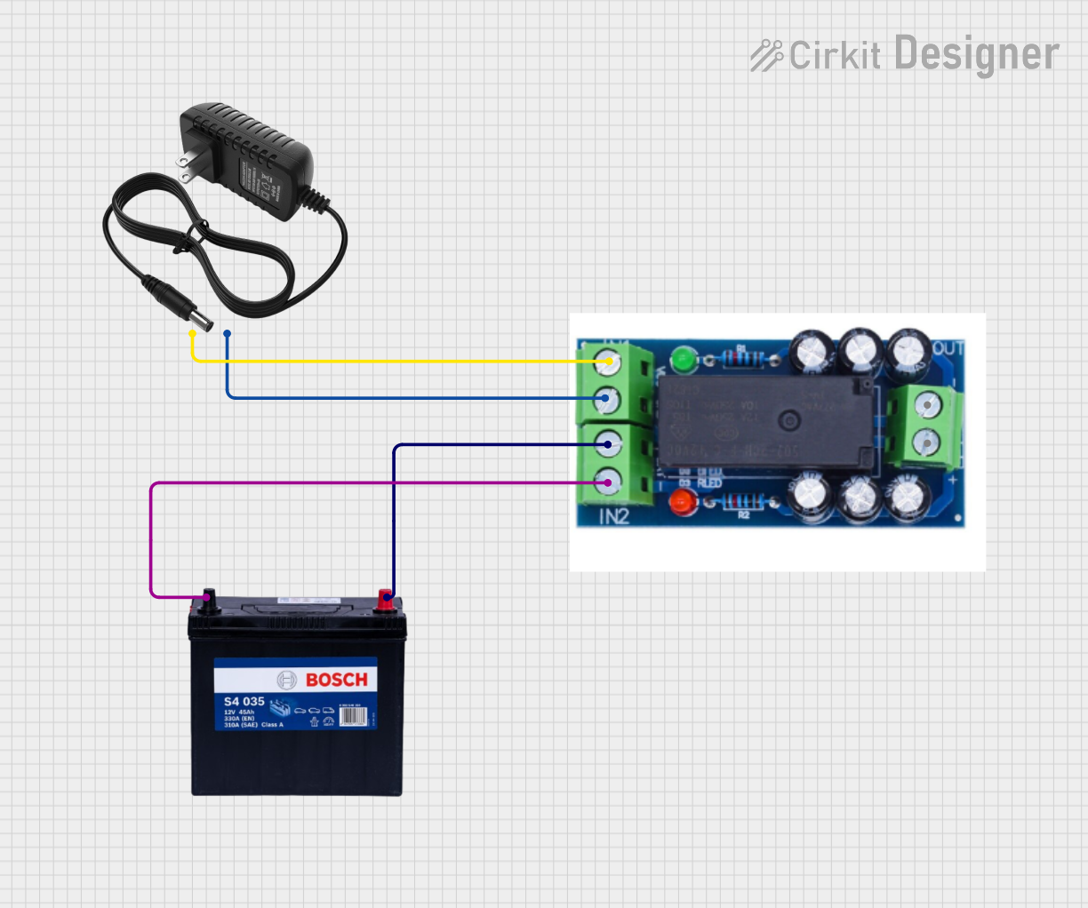
Example: Connecting to an Arduino UNO

While the Battery Switch ON/OFF 275A is not directly connected to an Arduino UNO, it can be used to control the power supply to an Arduino-based system. Below is an example of how to use the switch in such a setup:

  1. Connect the battery's positive terminal to Terminal 1 of the switch.
  2. Connect Terminal 2 of the switch to the VIN pin of the Arduino UNO via a voltage regulator (if the battery voltage exceeds 12V).
  3. Connect the battery's negative terminal to the GND pin of the Arduino UNO.
// Example Arduino code to blink an LED when powered through the Battery Switch
// Ensure the battery switch is in the "ON" position to supply power to the Arduino.

const int ledPin = 13; // Pin connected to the onboard LED

void setup() {
  pinMode(ledPin, OUTPUT); // Set the LED pin as an output
}

void loop() {
  digitalWrite(ledPin, HIGH); // Turn the LED on
  delay(1000);                // Wait for 1 second
  digitalWrite(ledPin, LOW);  // Turn the LED off
  delay(1000);                // Wait for 1 second
}

Troubleshooting and FAQs

Common Issues and Solutions

Issue Possible Cause Solution
Switch does not turn on the circuit. Loose or improper connections. Check and tighten all cable connections.
Overheating of the switch or cables. Cables not rated for 275A current. Use cables with appropriate current rating.
Corrosion on terminals. Exposure to moisture or saltwater. Clean terminals and apply a protective coating or use corrosion-resistant cables.
Switch is difficult to operate. Dirt or debris in the mechanism. Clean the switch and ensure it is free of obstructions.

FAQs

  1. Can this switch handle AC power?

    • No, the Battery Switch ON/OFF 275A is designed for DC power systems only.
  2. Is the switch waterproof?

    • Yes, the switch has an IP66 rating, making it dust-tight and resistant to water jets. However, it should not be submerged.
  3. Can I use this switch for a dual-battery system?

    • This switch is designed for single-battery systems. For dual-battery setups, consider using a dual-battery isolator switch.
  4. What is the maximum wire gauge supported?

    • The switch supports heavy-duty cables up to 1/0 AWG (50mm²).

By following this documentation, you can safely and effectively use the Battery Switch ON/OFF 275A in your projects.