How to Use IR Sensor Avoid Obstacles: Examples, Pinouts, and Specs
Introduction
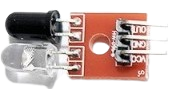
The IR Sensor Avoid Obstacles is an infrared sensor designed to detect and avoid obstacles by emitting and receiving IR signals. This sensor is commonly used in robotics, automation systems, and various electronic projects to enable devices to navigate around obstacles. It is a crucial component for creating autonomous robots and smart vehicles.
Explore Projects Built with IR Sensor Avoid Obstacles
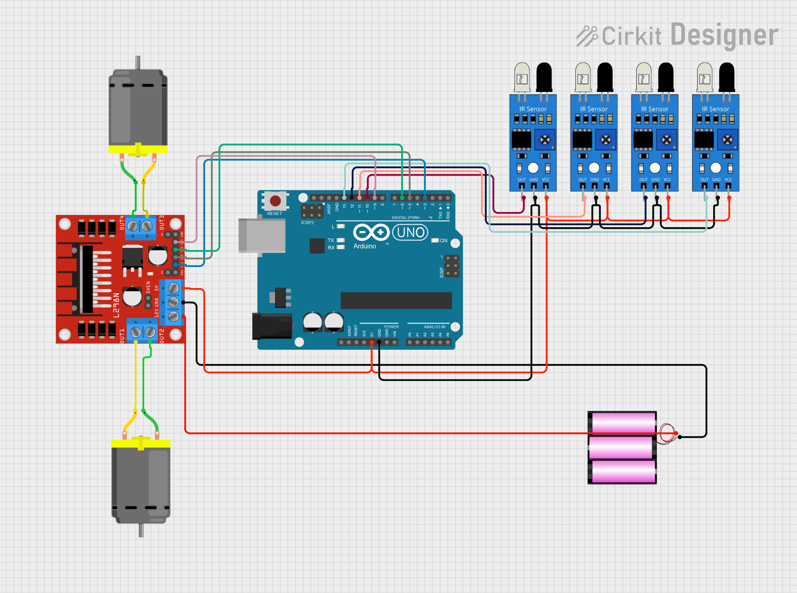
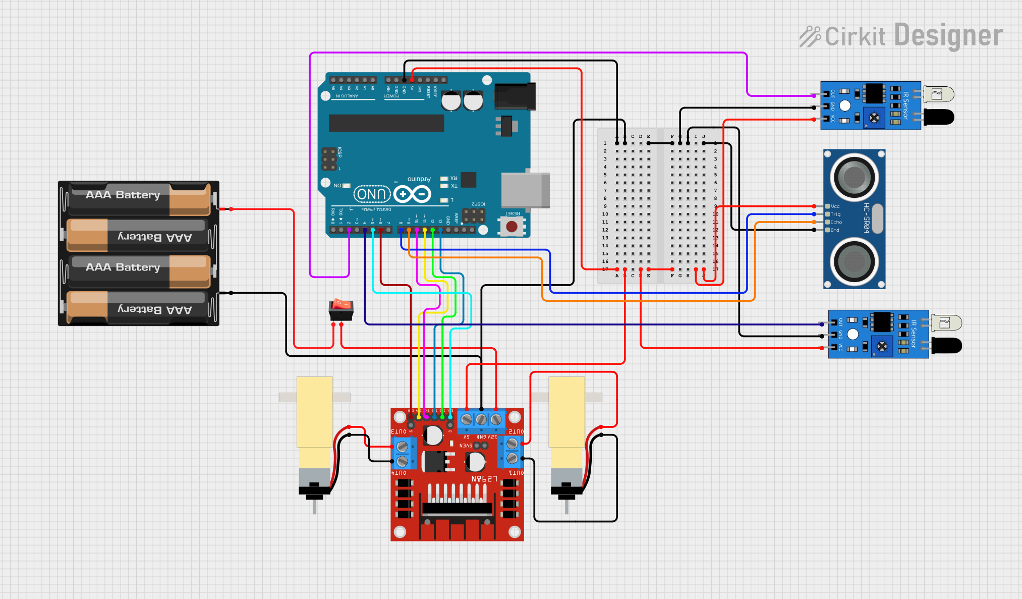
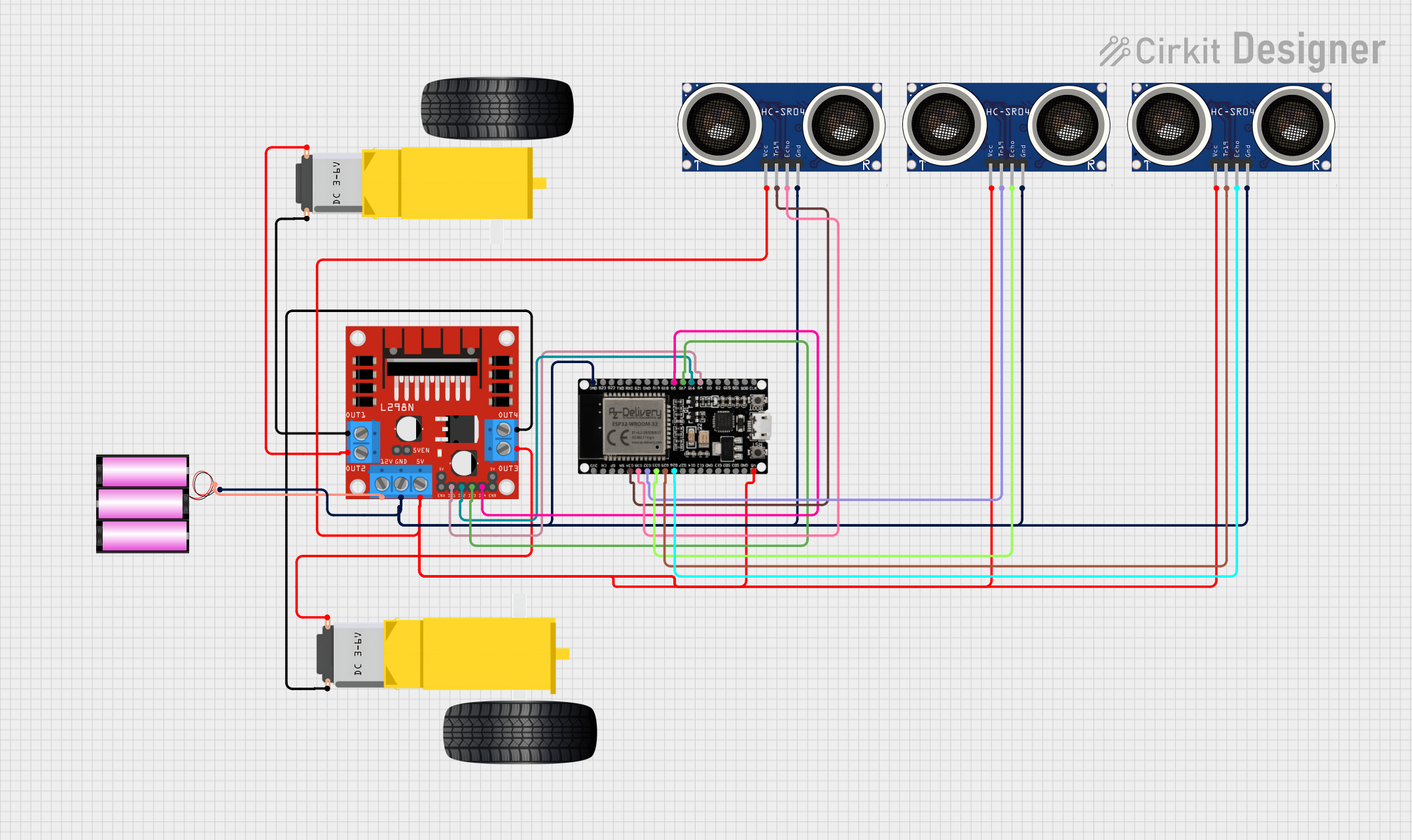
Explore Projects Built with IR Sensor Avoid Obstacles
Technical Specifications
Key Technical Details
| Parameter | Value |
|---|---|
| Operating Voltage | 3.0V - 5.0V |
| Operating Current | 20mA |
| Detection Range | 2cm - 30cm |
| Output Type | Digital (High/Low) |
| Dimensions | 3.2cm x 1.4cm x 0.7cm |
| Weight | 5g |
Pin Configuration and Descriptions
| Pin Number | Pin Name | Description |
|---|---|---|
| 1 | VCC | Power supply (3.0V - 5.0V) |
| 2 | GND | Ground |
| 3 | OUT | Digital output signal (High when obstacle detected, Low otherwise) |
Usage Instructions
How to Use the Component in a Circuit
- Power Connection: Connect the VCC pin to a 3.0V - 5.0V power supply and the GND pin to the ground of your circuit.
- Signal Connection: Connect the OUT pin to a digital input pin on your microcontroller (e.g., Arduino UNO).
Example Circuit Diagram
  VCC  ----> 5V (Arduino)
  GND  ----> GND (Arduino)
  OUT  ----> Digital Pin 2 (Arduino)
Arduino UNO Example Code
// IR Sensor Avoid Obstacles Example Code
// Connect the OUT pin of the IR sensor to digital pin 2 on the Arduino

const int irSensorPin = 2; // IR sensor OUT pin connected to digital pin 2
const int ledPin = 13;     // Onboard LED pin

void setup() {
  pinMode(irSensorPin, INPUT); // Set the IR sensor pin as input
  pinMode(ledPin, OUTPUT);     // Set the LED pin as output
  Serial.begin(9600);          // Initialize serial communication at 9600 baud
}

void loop() {
  int sensorValue = digitalRead(irSensorPin); // Read the value from the IR sensor

  if (sensorValue == HIGH) {
    // Obstacle detected
    digitalWrite(ledPin, HIGH); // Turn on the LED
    Serial.println("Obstacle detected!");
  } else {
    // No obstacle
    digitalWrite(ledPin, LOW);  // Turn off the LED
    Serial.println("No obstacle.");
  }

  delay(100); // Small delay to avoid serial monitor flooding
}
Important Considerations and Best Practices
- Power Supply: Ensure that the power supply voltage is within the specified range (3.0V - 5.0V) to avoid damaging the sensor.
- Interference: Avoid placing the sensor near sources of infrared interference, such as direct sunlight or other IR-emitting devices.
- Mounting: Position the sensor at an appropriate height and angle to effectively detect obstacles within the desired range.
Troubleshooting and FAQs
Common Issues Users Might Face
Sensor Not Detecting Obstacles:
- Solution: Check the power connections and ensure the sensor is receiving the correct voltage. Verify that the sensor is not obstructed or dirty.
False Positives/Negatives:
- Solution: Ensure there are no sources of infrared interference nearby. Adjust the sensor's position and angle for optimal detection.
Inconsistent Readings:
- Solution: Verify that the sensor is securely connected and not loose. Check for any loose wires or poor solder joints.
FAQs
Q1: What is the maximum detection range of the IR sensor?
- The maximum detection range is approximately 30cm.
Q2: Can the IR sensor detect transparent objects?
- No, the IR sensor may have difficulty detecting transparent objects as they do not reflect infrared light effectively.
Q3: Can I use multiple IR sensors in a single project?
- Yes, you can use multiple IR sensors in a single project. Ensure each sensor is connected to a separate digital input pin on your microcontroller.
Q4: How can I increase the detection range of the IR sensor?
- The detection range is fixed by the sensor's design. However, you can experiment with different mounting positions and angles to optimize detection.
By following this documentation, you should be able to effectively integrate and use the IR Sensor Avoid Obstacles in your electronic projects. Happy building!