How to Use Power MUX Click: Examples, Pinouts, and Specs
Introduction
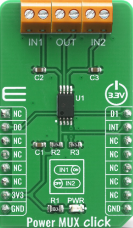
Power MUX Click is a power management module designed to facilitate the selection and seamless switching of multiple power sources to a single output. This component ensures efficient power distribution in electronic circuits, making it ideal for applications requiring redundancy or prioritization of power sources. It is commonly used in battery-powered devices, uninterruptible power supplies (UPS), and systems requiring automatic power source selection.
Explore Projects Built with Power MUX Click


Explore Projects Built with Power MUX Click
Common Applications and Use Cases
- Battery backup systems
- Redundant power supply systems
- Portable electronics with multiple power inputs
- IoT devices requiring uninterrupted power
- Power source prioritization in embedded systems
Technical Specifications
The Power MUX Click module is built to handle a wide range of power management tasks. Below are its key technical details:
Key Technical Details
- Input Voltage Range: 2.7V to 5.5V
- Output Voltage Range: Matches the selected input voltage
- Maximum Output Current: 3A (continuous)
- Switching Mechanism: Automatic or manual source selection
- Control Interface: GPIO or I2C (depending on configuration)
- Operating Temperature: -40°C to +85°C
- PCB Dimensions: 28.6mm x 25.4mm
Pin Configuration and Descriptions
The Power MUX Click module features a standard 8-pin interface. Below is the pinout description:
| Pin | Name | Type | Description |
|---|---|---|---|
| 1 | VIN1 | Power Input | Primary power source input (2.7V to 5.5V). |
| 2 | VIN2 | Power Input | Secondary power source input (2.7V to 5.5V). |
| 3 | VOUT | Power Output | Output voltage (matches selected input source). |
| 4 | GND | Ground | Common ground for the circuit. |
| 5 | SEL | Digital Input | Source selection pin (HIGH for VIN1, LOW for VIN2). |
| 6 | EN | Digital Input | Enable pin (HIGH to enable output, LOW to disable). |
| 7 | INT | Digital Output | Interrupt pin for status monitoring. |
| 8 | SDA/SCL | I2C Interface | Optional I2C communication pins for advanced control. |
Usage Instructions
The Power MUX Click module is straightforward to use in a circuit. Follow the steps below to integrate it into your design:
Basic Usage
- Connect Power Sources:
- Connect the primary power source to the
VIN1pin. - Connect the secondary power source to the
VIN2pin.
- Connect the primary power source to the
- Connect Output:
- Connect the load to the
VOUTpin.
- Connect the load to the
- Ground Connection:
- Ensure all components share a common ground by connecting to the
GNDpin.
- Ensure all components share a common ground by connecting to the
- Source Selection:
- Use the
SELpin to select the desired power source:- Set
SELHIGH to selectVIN1. - Set
SELLOW to selectVIN2.
- Set
- Use the
- Enable Output:
- Set the
ENpin HIGH to enable the output voltage.
- Set the
Important Considerations
- Ensure the input voltage does not exceed the specified range (2.7V to 5.5V).
- Do not exceed the maximum output current of 3A to avoid damage.
- Use decoupling capacitors near the input and output pins to reduce noise.
- If using the I2C interface, ensure proper pull-up resistors are connected to the
SDAandSCLlines.
Example: Using Power MUX Click with Arduino UNO
Below is an example of how to use the Power MUX Click module with an Arduino UNO to switch between two power sources:
// Define pin connections for Power MUX Click
#define SEL_PIN 7  // Pin connected to SEL (source selection)
#define EN_PIN 8   // Pin connected to EN (enable output)

void setup() {
  // Initialize pins as outputs
  pinMode(SEL_PIN, OUTPUT);
  pinMode(EN_PIN, OUTPUT);

  // Enable the Power MUX Click output
  digitalWrite(EN_PIN, HIGH);

  // Select the primary power source (VIN1)
  digitalWrite(SEL_PIN, HIGH);
}

void loop() {
  // Example: Toggle between power sources every 5 seconds
  digitalWrite(SEL_PIN, LOW);  // Switch to secondary power source (VIN2)
  delay(5000);                 // Wait for 5 seconds
  digitalWrite(SEL_PIN, HIGH); // Switch back to primary power source (VIN1)
  delay(5000);                 // Wait for 5 seconds
}
Troubleshooting and FAQs
Common Issues and Solutions
No Output Voltage:
- Ensure the
ENpin is set HIGH to enable the output. - Verify that at least one power source is connected and within the specified voltage range.
- Ensure the
Output Voltage Fluctuations:
- Check for loose connections or insufficient decoupling capacitors.
- Ensure the load does not exceed the maximum output current of 3A.
Module Overheating:
- Verify that the input voltage and current are within the specified limits.
- Ensure proper ventilation and heat dissipation around the module.
I2C Communication Issues:
- Confirm that pull-up resistors are connected to the
SDAandSCLlines. - Check the I2C address and ensure it matches the configuration in your code.
- Confirm that pull-up resistors are connected to the
FAQs
Q1: Can I use the Power MUX Click with only one power source?
A1: Yes, you can connect a single power source to either VIN1 or VIN2. Ensure the SEL pin is set accordingly.
Q2: What happens if both power sources are active?
A2: The module will select the source based on the SEL pin state. If SEL is HIGH, VIN1 is selected; if LOW, VIN2 is selected.
Q3: Is the switching between power sources seamless?
A3: Yes, the module is designed for seamless switching, minimizing disruptions to the output voltage.
Q4: Can I control the module using a microcontroller?
A4: Absolutely! The SEL and EN pins can be controlled via GPIO, and the I2C interface allows for advanced control and monitoring.