How to Use Usb C breakout board: Examples, Pinouts, and Specs
Introduction
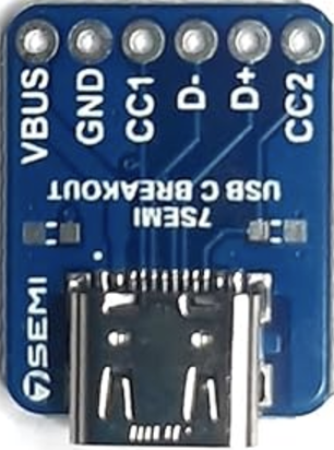
The USB-C Breakout Board (Manufacturer: SmartElex, Part ID: R177461) is a compact and versatile circuit board designed to provide easy access to the pins of a USB-C connector. This breakout board simplifies prototyping and testing of USB-C connections and functionalities, making it an essential tool for developers working on USB-C-based projects.
Explore Projects Built with Usb C breakout board


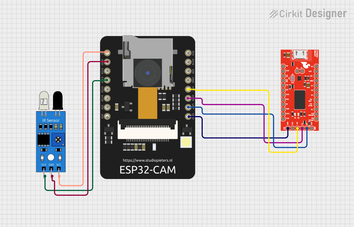
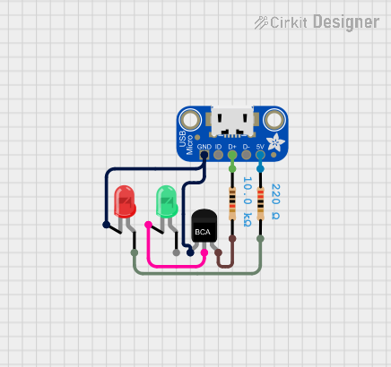
Explore Projects Built with Usb C breakout board
Common Applications and Use Cases
- Prototyping USB-C power delivery (PD) circuits.
- Testing USB-C data transfer and charging capabilities.
- Integrating USB-C connectors into custom electronic designs.
- Educational purposes for learning USB-C pinouts and functionality.
Technical Specifications
The USB-C Breakout Board is designed to expose the USB-C connector's pins for easy access. Below are the key technical details:
Key Specifications
- Connector Type: USB Type-C (24-pin)
- Voltage Rating: Up to 20V (supports USB Power Delivery)
- Current Rating: Up to 5A (depending on the connected power source)
- Board Dimensions: 25mm x 20mm
- Pin Pitch: 2.54mm (standard breadboard-compatible spacing)
- Material: FR4 PCB with gold-plated contacts for durability
Pin Configuration and Descriptions
The USB-C connector has 24 pins, but the breakout board typically exposes the most commonly used pins for prototyping. Below is the pin configuration:
| Pin Name | Description | Notes |
|---|---|---|
| GND | Ground | Common ground for power and data |
| VBUS | Power input/output (5V-20V) | Voltage depends on USB-C power source |
| CC1, CC2 | Configuration Channel pins | Used for USB-C cable orientation detection |
| D+ | USB 2.0 Data Positive | For USB 2.0 communication |
| D- | USB 2.0 Data Negative | For USB 2.0 communication |
| TX1+, TX1- | USB 3.x Transmit Differential Pair | For high-speed data transfer |
| RX1+, RX1- | USB 3.x Receive Differential Pair | For high-speed data transfer |
| TX2+, TX2- | USB 3.x Transmit Differential Pair | Alternate orientation for high-speed data |
| RX2+, RX2- | USB 3.x Receive Differential Pair | Alternate orientation for high-speed data |
| SBU1, SBU2 | Sideband Use pins | Used for alternate modes (e.g., audio) |
Note: Not all pins may be exposed on the breakout board. Refer to the specific board layout for details.
Usage Instructions
How to Use the USB-C Breakout Board in a Circuit
- Connect the Breakout Board to a Breadboard: The 2.54mm pin spacing allows the breakout board to be easily inserted into a standard breadboard for prototyping.
- Power the Board: Connect the VBUS and GND pins to your power source. Ensure the voltage and current ratings are within the board's specifications.
- Access Data Pins: Use the D+, D-, TX, and RX pins for USB data communication. For USB 2.0, only D+ and D- are required.
- Use CC Pins for Orientation Detection: The CC1 and CC2 pins can be used to detect the orientation of the USB-C cable and negotiate power delivery if needed.
- Test Alternate Modes: If your project requires alternate modes (e.g., DisplayPort or audio), use the SBU pins as specified in your design.
Important Considerations and Best Practices
- Voltage and Current Limits: Ensure the connected power source does not exceed the board's voltage (20V) and current (5A) ratings.
- Cable Orientation: USB-C is reversible, so the CC pins help determine the correct orientation.
- Avoid Short Circuits: Double-check connections to prevent shorting adjacent pins, especially when working with high currents.
- USB Power Delivery (PD): If using USB PD, additional circuitry is required to negotiate higher voltages (e.g., 9V, 15V, 20V).
Example: Connecting to an Arduino UNO
The USB-C breakout board can be used to power an Arduino UNO or communicate with it via USB. Below is an example of powering the Arduino UNO:
- Connect the VBUS pin of the breakout board to the VIN pin of the Arduino UNO.
- Connect the GND pin of the breakout board to the GND pin of the Arduino UNO.
Here is an example Arduino sketch to read data from a USB-C device connected to the breakout board:
// Example Arduino sketch for reading data from a USB-C device
// connected to the breakout board via D+ and D- pins.

void setup() {
  Serial.begin(9600); // Initialize serial communication at 9600 baud
  Serial.println("USB-C Breakout Board Test");
}

void loop() {
  if (Serial.available() > 0) {
    // Read incoming data from the USB-C device
    char data = Serial.read();
    Serial.print("Received: ");
    Serial.println(data);
  }
}
Note: This example assumes the USB-C device is configured to send data over the D+ and D- pins.
Troubleshooting and FAQs
Common Issues and Solutions
No Power on VBUS Pin
- Cause: The USB-C cable may not be connected to a power source.
- Solution: Ensure the USB-C cable is plugged into a power adapter or powered USB port.
Data Communication Fails
- Cause: Incorrect connections to D+ and D- pins.
- Solution: Verify the wiring and ensure the device supports USB 2.0 or 3.x communication.
Overheating
- Cause: Exceeding the voltage or current ratings.
- Solution: Use a power source within the specified limits (max 20V, 5A).
Cable Orientation Not Detected
- Cause: CC pins not connected or misconfigured.
- Solution: Check the CC1 and CC2 pin connections and ensure proper pull-up or pull-down resistors are used.
FAQs
Q: Can this breakout board be used for USB-C Power Delivery (PD)?
- A: Yes, but additional circuitry is required to negotiate higher voltages (e.g., 9V, 15V, 20V).
Q: Is the breakout board compatible with USB 3.x?
- A: Yes, the board exposes TX and RX differential pairs for USB 3.x high-speed data transfer.
Q: Can I use this board for alternate modes like DisplayPort?
- A: Yes, the SBU pins can be used for alternate modes, but additional configuration is required.
Q: Does the board support reverse polarity protection?
- A: No, ensure correct polarity when connecting power to avoid damage.
This documentation provides a comprehensive guide to using the SmartElex USB-C Breakout Board (R177461) for your prototyping and testing needs.