How to Use 555 Relay: Examples, Pinouts, and Specs
Introduction
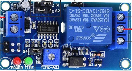
The 555 Relay (Manufacturer: ANMBEST, Part ID: B088Q9DQNM) is a versatile electronic component that combines the functionality of a 555 timer IC with a relay module. It is widely used for timing, switching, and pulse generation in electronic circuits. The 555 Relay can operate in multiple modes, including monostable, astable, and bistable, making it suitable for applications such as timers, oscillators, flip-flops, and automated control systems.
Explore Projects Built with 555 Relay

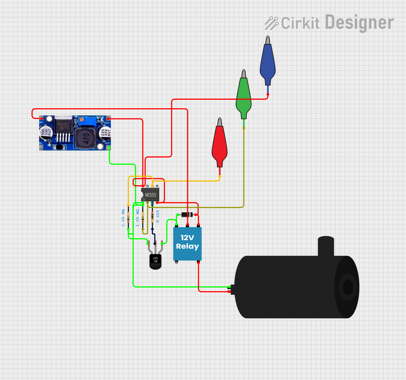
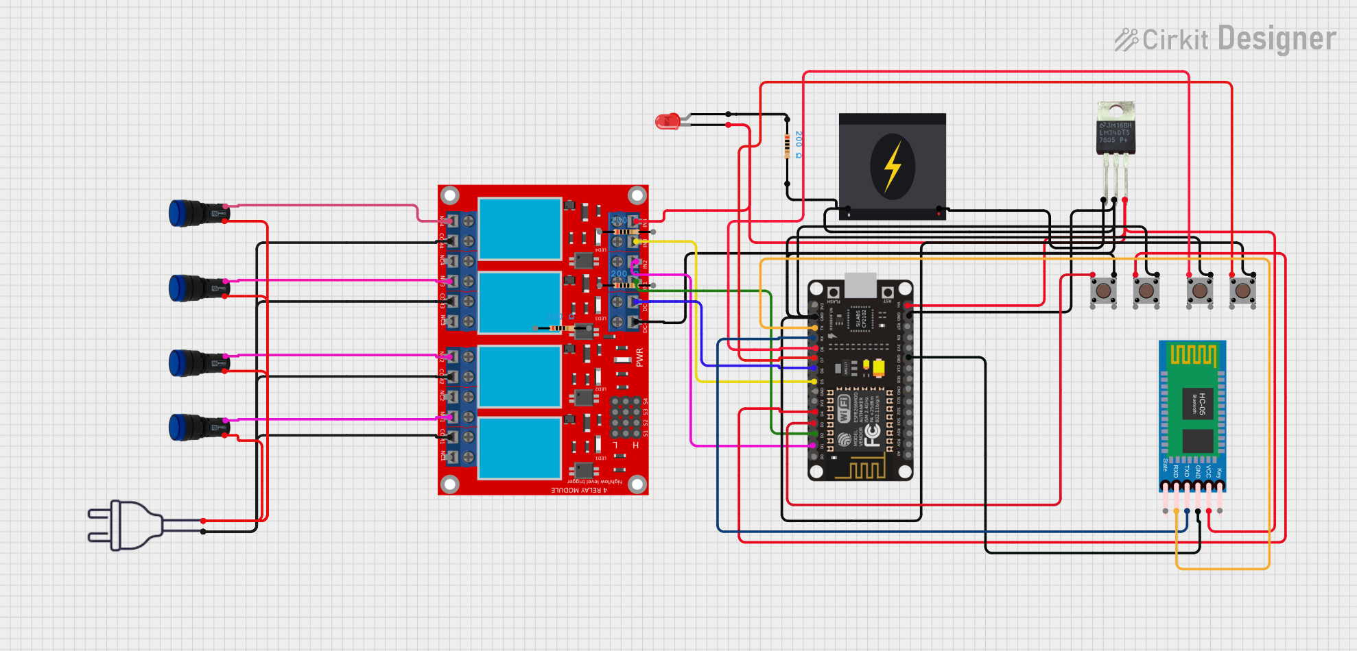

Explore Projects Built with 555 Relay
Common Applications
- Timers: Used in delay circuits for turning devices on or off after a set time.
- Oscillators: Generates square wave signals for clock pulses or frequency generation.
- Switching Circuits: Controls high-power devices using low-power signals.
- Pulse Generation: Produces precise pulses for triggering other components.
- Automation: Used in home automation, industrial control, and robotics.
Technical Specifications
Below are the key technical details of the ANMBEST 555 Relay module:
General Specifications
- Operating Voltage: 5V DC
- Relay Output Voltage: Up to 250V AC or 30V DC
- Relay Output Current: Up to 10A
- Trigger Voltage: 0-5V (logic level)
- Modes of Operation: Monostable, Astable, Bistable
- PCB Dimensions: 50mm x 26mm x 18mm
Pin Configuration and Descriptions
The 555 Relay module typically has the following pin configuration:
| Pin Name | Description |
|---|---|
| VCC | Power supply input (5V DC). |
| GND | Ground connection. |
| TRIG | Trigger input pin for starting the timer (active low). |
| OUT | Output pin for controlling the relay. |
| RESET | Resets the timer (active low). |
| CTRL | Control voltage pin for adjusting the threshold voltage (optional). |
| THR | Threshold pin for voltage comparison to end the timing cycle. |
| DIS | Discharge pin for capacitor discharge during timing cycles. |
| RELAY NO | Normally Open (NO) terminal of the relay. |
| RELAY NC | Normally Closed (NC) terminal of the relay. |
| RELAY COM | Common terminal of the relay. |
Usage Instructions
How to Use the 555 Relay in a Circuit
- Power the Module: Connect the VCC pin to a 5V DC power source and the GND pin to ground.
- Choose the Mode:
- Monostable Mode: Connect a capacitor and resistor to set the timing interval. Trigger the timer using the TRIG pin.
- Astable Mode: Connect external resistors and a capacitor to generate a continuous square wave.
- Bistable Mode: Use the TRIG and RESET pins to toggle the relay state.
- Connect the Load: Attach the load to the relay terminals (NO, NC, and COM) based on your switching requirements.
- Trigger the Relay: Apply a low signal to the TRIG pin to activate the relay in monostable mode or configure the circuit for continuous operation in astable mode.
Important Considerations
- Ensure the power supply voltage does not exceed 5V to avoid damaging the module.
- Use a flyback diode across the relay coil to protect the circuit from voltage spikes.
- For high-current loads, ensure the relay's current rating is not exceeded.
- Use proper heat dissipation techniques if the relay operates for extended periods.
Example: Using the 555 Relay with an Arduino UNO
Below is an example of how to use the 555 Relay in monostable mode with an Arduino UNO:
// Example: Controlling a 555 Relay in monostable mode with Arduino UNO

const int relayPin = 7;  // Pin connected to the relay module's TRIG pin
const int buttonPin = 2; // Pin connected to a push button for triggering

void setup() {
  pinMode(relayPin, OUTPUT);  // Set relay pin as output
  pinMode(buttonPin, INPUT_PULLUP); // Set button pin as input with pull-up resistor
}

void loop() {
  if (digitalRead(buttonPin) == LOW) {
    // If button is pressed (active low)
    digitalWrite(relayPin, HIGH); // Trigger the relay
    delay(1000); // Keep the relay on for 1 second
    digitalWrite(relayPin, LOW);  // Turn off the relay
  }
}
Notes:
- Adjust the
delay()value to change the relay activation time. - Ensure the relay module is properly powered and connected to the Arduino.
Troubleshooting and FAQs
Common Issues and Solutions
Relay Not Activating:
- Check the power supply voltage (must be 5V DC).
- Verify the TRIG pin is receiving the correct signal (active low).
- Ensure the load connected to the relay is within its voltage and current ratings.
Unstable Operation:
- Add a decoupling capacitor (e.g., 0.1µF) across the power supply pins to reduce noise.
- Verify the external resistors and capacitors are correctly connected for the desired mode.
Overheating:
- Ensure the relay is not switching a load that exceeds its current rating.
- Use a heatsink or cooling fan if the relay operates continuously.
Arduino Not Controlling the Relay:
- Confirm the Arduino pin is set as an output in the code.
- Check the wiring between the Arduino and the relay module.
FAQs
Q1: Can the 555 Relay operate at voltages higher than 5V?
No, the module is designed to operate at 5V DC. Using higher voltages may damage the circuit.
Q2: How do I calculate the timing interval in monostable mode?
The timing interval is determined by the formula:T = 1.1 * R * C
Where R is the resistance in ohms and C is the capacitance in farads.
Q3: Can I use the 555 Relay for AC loads?
Yes, the relay can switch AC loads up to 250V, provided the current does not exceed 10A.
Q4: What is the purpose of the CTRL pin?
The CTRL pin allows fine-tuning of the threshold voltage. It is optional and can be left unconnected in most applications.
By following this documentation, users can effectively integrate the ANMBEST 555 Relay (B088Q9DQNM) into their projects for reliable timing and switching operations.