Cirkit Designer Logo
Cirkit Designer
Your all-in-one circuit design IDE
Home / 
Component Documentation

How to Use Endstop: Examples, Pinouts, and Specs

Image of Endstop
Cirkit Designer LogoDesign with Endstop in Cirkit Designer

Introduction

An endstop is a critical safety and precision device used in 3D printers, CNC machines, and other automated systems where precise control of motion is required. It serves as a limit switch that the machine's controller uses to determine the end of the travel range for a moving part, such as an axis of a 3D printer. When the moving part comes into contact with the endstop, it sends a signal to the controller to halt movement, preventing damage to the machine and ensuring the accuracy of the operation.

Explore Projects Built with Endstop

Use Cirkit Designer to design, explore, and prototype these projects online. Some projects support real-time simulation. Click "Open Project" to start designing instantly!
ESP32-Based Sensor Monitoring System with OLED Display and E-Stop
Image of MVP_design: A project utilizing Endstop in a practical application
This circuit features an ESP32 microcontroller that interfaces with a variety of sensors and output devices. It is powered by a Lipo battery through a buck converter, ensuring a stable voltage supply. The ESP32 collects data from a DHT11 temperature and humidity sensor and a vibration sensor, controls a buzzer, and displays information on an OLED screen. An emergency stop (E Stop) is connected for safety purposes, allowing the system to be quickly deactivated.
Cirkit Designer LogoOpen Project in Cirkit Designer
Arduino Nano Controlled Relay System with Safety Interlocks
Image of HYD: A project utilizing Endstop in a practical application
This circuit includes an Arduino Nano microcontroller interfaced with multiple pushbuttons, limit switches, an emergency stop, a 2-channel relay module, and a 1-channel relay module. The Arduino controls the relay modules based on inputs from the pushbuttons and limit switches, which likely serve as user interfaces and position or safety sensors. The circuit is powered by a 5V power supply unit (PSU), which is connected to an AC supply, and the emergency stop is configured to potentially interrupt the circuit for safety purposes.
Cirkit Designer LogoOpen Project in Cirkit Designer
Electromechanical Pump Control Circuit with Emergency Stop
Image of Pelton.: A project utilizing Endstop in a practical application
This circuit is designed to control a pump using a contactor that is manually operated by a switch and can be overridden by an emergency stop. The contactor enables power from an AC power outlet to the pump, and the emergency stop can interrupt the power circuit for safety purposes.
Cirkit Designer LogoOpen Project in Cirkit Designer
CNC Machine with Limit Switch Integration
Image of CNC: A project utilizing Endstop in a practical application
This circuit connects a limit switch to a CNC machine, allowing the CNC to receive signals from the limit switch. The limit switch is powered by the CNC's 3.3V supply and shares a common ground with the CNC.
Cirkit Designer LogoOpen Project in Cirkit Designer

Explore Projects Built with Endstop

Use Cirkit Designer to design, explore, and prototype these projects online. Some projects support real-time simulation. Click "Open Project" to start designing instantly!
Image of MVP_design: A project utilizing Endstop in a practical application
ESP32-Based Sensor Monitoring System with OLED Display and E-Stop
This circuit features an ESP32 microcontroller that interfaces with a variety of sensors and output devices. It is powered by a Lipo battery through a buck converter, ensuring a stable voltage supply. The ESP32 collects data from a DHT11 temperature and humidity sensor and a vibration sensor, controls a buzzer, and displays information on an OLED screen. An emergency stop (E Stop) is connected for safety purposes, allowing the system to be quickly deactivated.
Cirkit Designer LogoOpen Project in Cirkit Designer
Image of HYD: A project utilizing Endstop in a practical application
Arduino Nano Controlled Relay System with Safety Interlocks
This circuit includes an Arduino Nano microcontroller interfaced with multiple pushbuttons, limit switches, an emergency stop, a 2-channel relay module, and a 1-channel relay module. The Arduino controls the relay modules based on inputs from the pushbuttons and limit switches, which likely serve as user interfaces and position or safety sensors. The circuit is powered by a 5V power supply unit (PSU), which is connected to an AC supply, and the emergency stop is configured to potentially interrupt the circuit for safety purposes.
Cirkit Designer LogoOpen Project in Cirkit Designer
Image of Pelton.: A project utilizing Endstop in a practical application
Electromechanical Pump Control Circuit with Emergency Stop
This circuit is designed to control a pump using a contactor that is manually operated by a switch and can be overridden by an emergency stop. The contactor enables power from an AC power outlet to the pump, and the emergency stop can interrupt the power circuit for safety purposes.
Cirkit Designer LogoOpen Project in Cirkit Designer
Image of CNC: A project utilizing Endstop in a practical application
CNC Machine with Limit Switch Integration
This circuit connects a limit switch to a CNC machine, allowing the CNC to receive signals from the limit switch. The limit switch is powered by the CNC's 3.3V supply and shares a common ground with the CNC.
Cirkit Designer LogoOpen Project in Cirkit Designer

Common Applications and Use Cases

  • Determining the home position in 3D printers
  • Setting limits on CNC machine axes
  • Position control in robotic arms
  • Safety interlocks in automated systems

Technical Specifications

Key Technical Details

  • Voltage Rating: 5V DC (typical for digital logic level compatibility)
  • Current Rating: 10mA to 20mA (varies by model)
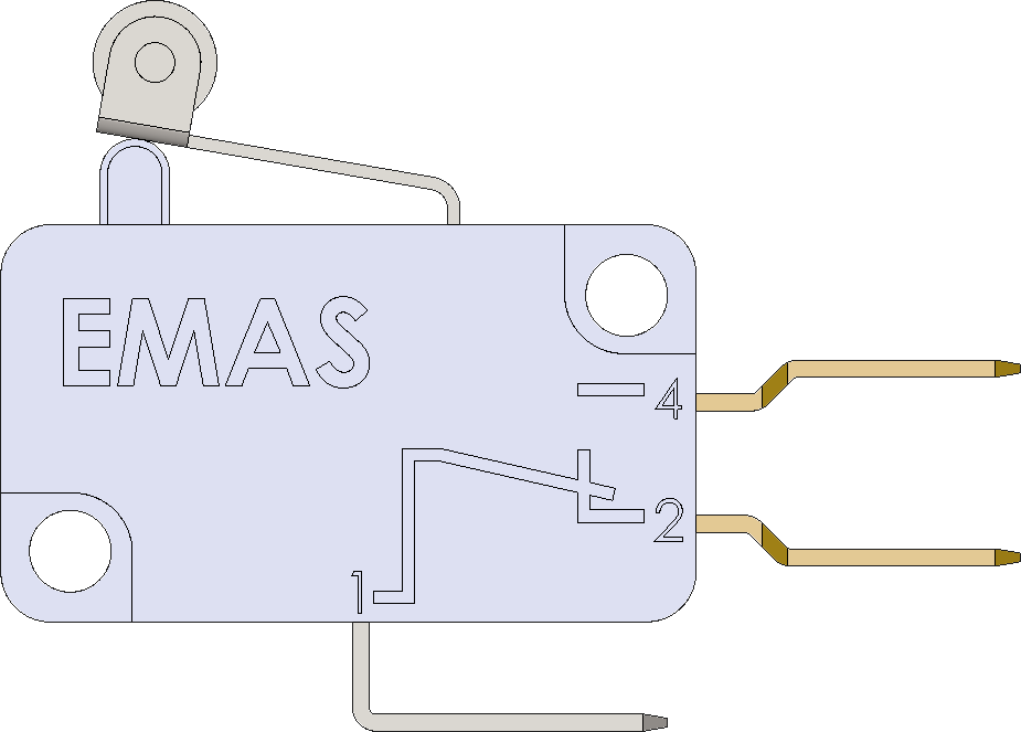
  • Contact Type: Mechanical (microswitch) or Non-contact (magnetic or optical)
  • Output Type: Digital signal (High or Low level)

Pin Configuration and Descriptions

Pin Number Description Notes
1 Signal (SIG) Outputs a digital signal
2 Ground (GND) Connect to system ground
3 Power (VCC) Connect to 5V power supply

Usage Instructions

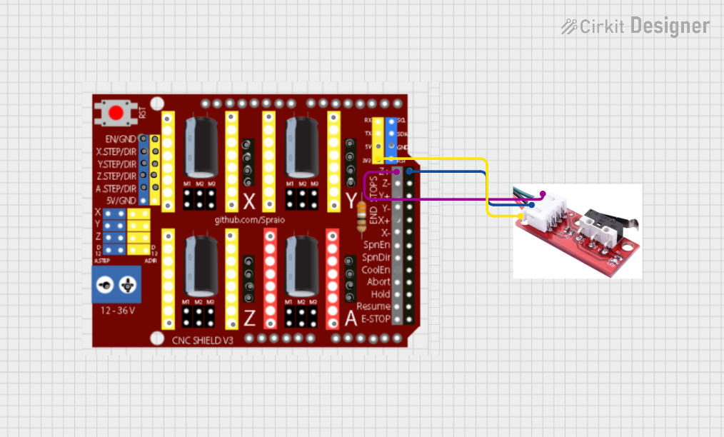
How to Use the Component in a Circuit

  1. Connect the Power (VCC) Pin: Connect the VCC pin to a 5V power supply from your controller board, such as an Arduino UNO.
  2. Connect the Ground (GND) Pin: Connect the GND pin to the ground on your controller board.
  3. Connect the Signal (SIG) Pin: Connect the SIG pin to a digital input pin on your controller board.

Important Considerations and Best Practices

  • Ensure that the endstop is securely mounted so that it can accurately detect the moving part.
  • Use pull-up or pull-down resistors as necessary to avoid floating inputs when the switch is open.
  • Debounce the signal either through hardware or software to prevent false triggering due to mechanical vibrations.
  • Test the endstop functionality before running the machine at full speed to ensure proper operation.

Example Code for Arduino UNO

// Define the pin connected to the endstop
const int endstopPin = 2;

void setup() {
  // Set the endstop pin as an input
  pinMode(endstopPin, INPUT_PULLUP);
  // Initialize serial communication
  Serial.begin(9600);
}

void loop() {
  // Read the state of the endstop
  int endstopState = digitalRead(endstopPin);

  // Check if the endstop is triggered (assuming normally open)
  if (endstopState == LOW) {
    // Endstop is triggered, stop the motion
    Serial.println("Endstop triggered!");
    // Implement motion stop logic here
  } else {
    // Endstop is not triggered, continue motion
    Serial.println("Endstop not triggered.");
    // Implement motion logic here
  }

  // Small delay to reduce serial message frequency
  delay(200);
}

Troubleshooting and FAQs

Common Issues Users Might Face

  • Endstop Not Triggering: Check the wiring and ensure that the endstop is properly connected to the controller. Verify that the moving part is actually making contact with the endstop.
  • False Triggering: This can be caused by noise or vibrations. Implement hardware debouncing with a capacitor or use software debouncing techniques.
  • Endstop Always Triggered: Ensure that the endstop is not stuck in the triggered position and that there are no shorts in the wiring.

Solutions and Tips for Troubleshooting

  • Testing the Endstop: Use a multimeter to check for continuity when the endstop is triggered.
  • LED Indicator: Some endstops come with an LED indicator that lights up when triggered. This can be a quick visual aid for troubleshooting.
  • Software Debugging: Use serial print statements to debug the state of the endstop in your code.

FAQs

Q: Can I use an endstop with a voltage rating different from 5V? A: It is essential to use an endstop with a voltage rating compatible with your controller board. Using a higher voltage may damage the board.

Q: How do I know if my endstop is normally open (NO) or normally closed (NC)? A: You can determine this by checking the continuity of the endstop in its resting state with a multimeter. NO endstops will not have continuity until triggered, while NC endstops will have continuity until triggered.

Q: Can I use multiple endstops on a single axis? A: Yes, you can use multiple endstops for added safety or to define multiple stopping points along an axis. Each endstop should be connected to a separate input pin on the controller.

This documentation provides a comprehensive guide to using an endstop with an electronic system. By following the instructions and best practices outlined above, users can ensure the safe and accurate operation of their machines.