How to Use ADUM1401BRWZ: Examples, Pinouts, and Specs
Introduction
The ADUM1401BRWZ is a high-performance digital isolator that provides galvanic isolation between two circuits. It utilizes Analog Devices' iCoupler® technology to achieve high-speed data transfer while maintaining electrical isolation. This component is ideal for applications requiring robust isolation in data communication, such as industrial control systems, medical devices, power supplies, and motor control systems. Its compact design and high reliability make it a popular choice for engineers working on safety-critical and noise-sensitive systems.
Explore Projects Built with ADUM1401BRWZ


Explore Projects Built with ADUM1401BRWZ
Technical Specifications
Key Specifications
- Isolation Voltage: 2.5 kV RMS (minimum)
- Data Rate: Up to 90 Mbps
- Propagation Delay: 13 ns (typical)
- Supply Voltage: 3.0 V to 5.5 V
- Operating Temperature Range: -40°C to +105°C
- Channel Configuration: 4 channels (3 forward, 1 reverse)
- Power Consumption: 1.1 mA per channel (typical at 1 Mbps)
- Package Type: 16-lead SOIC (Wide Body)
Pin Configuration and Descriptions
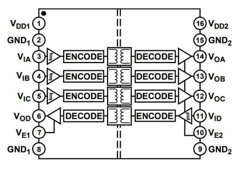
The ADUM1401BRWZ is housed in a 16-lead SOIC package. The pinout and descriptions are as follows:
| Pin Number | Pin Name | Description |
|---|---|---|
| 1 | VDD1 | Supply voltage for side 1 (3.0 V to 5.5 V). |
| 2 | GND1 | Ground for side 1. |
| 3 | VIA | Input signal for channel A (side 1). |
| 4 | VIB | Input signal for channel B (side 1). |
| 5 | VIC | Input signal for channel C (side 1). |
| 6 | GND1 | Ground for side 1 (duplicate pin for improved grounding). |
| 7 | NC | No connection (leave unconnected). |
| 8 | NC | No connection (leave unconnected). |
| 9 | GND2 | Ground for side 2. |
| 10 | VOD | Output signal for channel D (side 2). |
| 11 | VOC | Output signal for channel C (side 2). |
| 12 | VOB | Output signal for channel B (side 2). |
| 13 | VOA | Output signal for channel A (side 2). |
| 14 | GND2 | Ground for side 2 (duplicate pin for improved grounding). |
| 15 | VDD2 | Supply voltage for side 2 (3.0 V to 5.5 V). |
| 16 | NC | No connection (leave unconnected). |
Usage Instructions
How to Use the ADUM1401BRWZ in a Circuit
- Power Supply: Connect VDD1 and VDD2 to separate power supplies (3.0 V to 5.5 V). Ensure that GND1 and GND2 are isolated from each other to maintain galvanic isolation.
- Signal Connections:
- Connect the input signals to VIA, VIB, and VIC on side 1.
- The corresponding outputs (VOA, VOB, VOC) on side 2 will replicate the input signals.
- For the reverse channel, connect the input signal to VOD on side 2, and the output will appear on side 1.
- Bypass Capacitors: Place decoupling capacitors (e.g., 0.1 µF) close to VDD1 and VDD2 to reduce noise and ensure stable operation.
- Unused Pins: Leave NC (No Connection) pins unconnected.
Important Considerations and Best Practices
- Isolation Barrier: Ensure that the isolation barrier between side 1 and side 2 is not compromised by external connections or PCB layout.
- Data Rate: Operate within the specified data rate (up to 90 Mbps) to avoid signal integrity issues.
- Thermal Management: Ensure adequate ventilation or heat dissipation if operating at high ambient temperatures.
- PCB Layout: Use separate ground planes for GND1 and GND2 to maintain isolation and minimize noise coupling.
Example: Connecting the ADUM1401BRWZ to an Arduino UNO
The ADUM1401BRWZ can be used to isolate communication between an Arduino UNO and another device. Below is an example of how to transmit a digital signal from the Arduino to an isolated circuit.
Circuit Connections
- Connect the Arduino's digital output pin (e.g., D3) to VIA (Pin 3) of the ADUM1401BRWZ.
- Connect VOA (Pin 13) to the input of the isolated circuit.
- Power VDD1 from the Arduino's 5V pin and GND1 from the Arduino's GND.
- Power VDD2 and GND2 from the isolated circuit's power supply.
Arduino Code Example
// Example code to send a digital signal through the ADUM1401BRWZ
const int signalPin = 3; // Pin connected to VIA (Pin 3 of ADUM1401BRWZ)

void setup() {
  pinMode(signalPin, OUTPUT); // Set the signal pin as an output
}

void loop() {
  digitalWrite(signalPin, HIGH); // Send a HIGH signal
  delay(1000); // Wait for 1 second
  digitalWrite(signalPin, LOW);  // Send a LOW signal
  delay(1000); // Wait for 1 second
}
Troubleshooting and FAQs
Common Issues and Solutions
No Signal on Output Pins:
- Verify that VDD1 and VDD2 are powered correctly and within the specified voltage range.
- Check the input signal connections and ensure they are properly driven.
Signal Distortion or Noise:
- Ensure proper decoupling capacitors are placed near VDD1 and VDD2.
- Verify that the data rate does not exceed 90 Mbps.
Loss of Isolation:
- Inspect the PCB layout to ensure that GND1 and GND2 are not inadvertently connected.
- Avoid routing high-voltage traces near the isolation barrier.
Overheating:
- Check for excessive current draw on VDD1 or VDD2.
- Ensure the component is operating within the specified temperature range.
FAQs
Q1: Can the ADUM1401BRWZ be used for bidirectional communication?
A1: Yes, the ADUM1401BRWZ supports bidirectional communication with its 3 forward channels and 1 reverse channel.
Q2: What is the maximum isolation voltage?
A2: The ADUM1401BRWZ provides a minimum isolation voltage of 2.5 kV RMS.
Q3: Can I use the ADUM1401BRWZ with a 3.3V system?
A3: Yes, the ADUM1401BRWZ is compatible with supply voltages ranging from 3.0 V to 5.5 V.
Q4: Do I need external pull-up resistors for the input pins?
A4: No, the ADUM1401BRWZ does not require external pull-up resistors for its input pins.