How to Use ESP32-S3-CAM: Examples, Pinouts, and Specs
Introduction
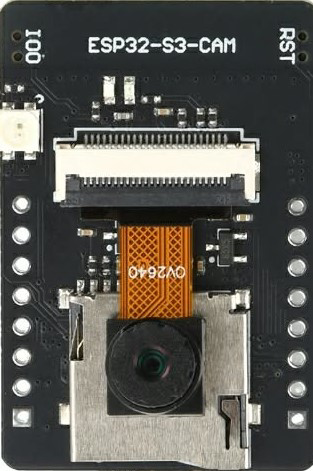
The ESP32-S3-CAM is a low-cost, low-power system on a chip (SoC) developed by Arduino, featuring integrated Wi-Fi and Bluetooth capabilities. It is specifically designed for applications requiring image capture and processing, thanks to its built-in camera interface. This module is ideal for IoT applications, smart devices, and projects involving video streaming, facial recognition, or object detection.
Explore Projects Built with ESP32-S3-CAM


Explore Projects Built with ESP32-S3-CAM
Common Applications and Use Cases
- Smart home devices (e.g., security cameras, video doorbells)
- IoT projects requiring image or video processing
- Facial recognition and object detection systems
- Remote monitoring and surveillance
- Educational and prototyping projects
Technical Specifications
The ESP32-S3-CAM is a powerful and versatile module with the following key specifications:
| Parameter | Value |
|---|---|
| Manufacturer | Arduino |
| Manufacturer Part ID | UNO |
| Processor | Dual-core Xtensa® LX7 (240 MHz) |
| Wireless Connectivity | Wi-Fi 802.11 b/g/n and Bluetooth 5.0 |
| Camera Interface | Supports external cameras (e.g., OV2640, OV5640) |
| Flash Memory | 8 MB PSRAM, 16 MB Flash |
| GPIO Pins | 44 GPIO pins (multipurpose, including PWM, ADC, I2C, SPI, UART, etc.) |
| Operating Voltage | 3.3V |
| Power Consumption | Ultra-low power consumption in deep sleep mode |
| Dimensions | Compact form factor (40mm x 20mm) |
Pin Configuration and Descriptions
The ESP32-S3-CAM features a variety of pins for interfacing with peripherals. Below is a table summarizing the key pins:
| Pin Name | Type | Description |
|---|---|---|
| 3V3 | Power | 3.3V power input |
| GND | Power | Ground connection |
| GPIO0 | Digital I/O | General-purpose I/O, used for boot mode selection |
| GPIO1 | Digital I/O | General-purpose I/O, UART TX |
| GPIO2 | Digital I/O | General-purpose I/O, often used for camera data |
| GPIO3 | Digital I/O | General-purpose I/O, UART RX |
| GPIO12 | Digital I/O | General-purpose I/O, often used for camera clock |
| GPIO13 | Digital I/O | General-purpose I/O, often used for camera reset |
| GPIO21 | Digital I/O | General-purpose I/O, I2C SDA |
| GPIO22 | Digital I/O | General-purpose I/O, I2C SCL |
| GPIO33 | Digital I/O | General-purpose I/O, PWM output |
| RESET | Reset | Resets the module |
Note: The exact pin usage may vary depending on the specific camera module and peripherals connected.
Usage Instructions
How to Use the ESP32-S3-CAM in a Circuit
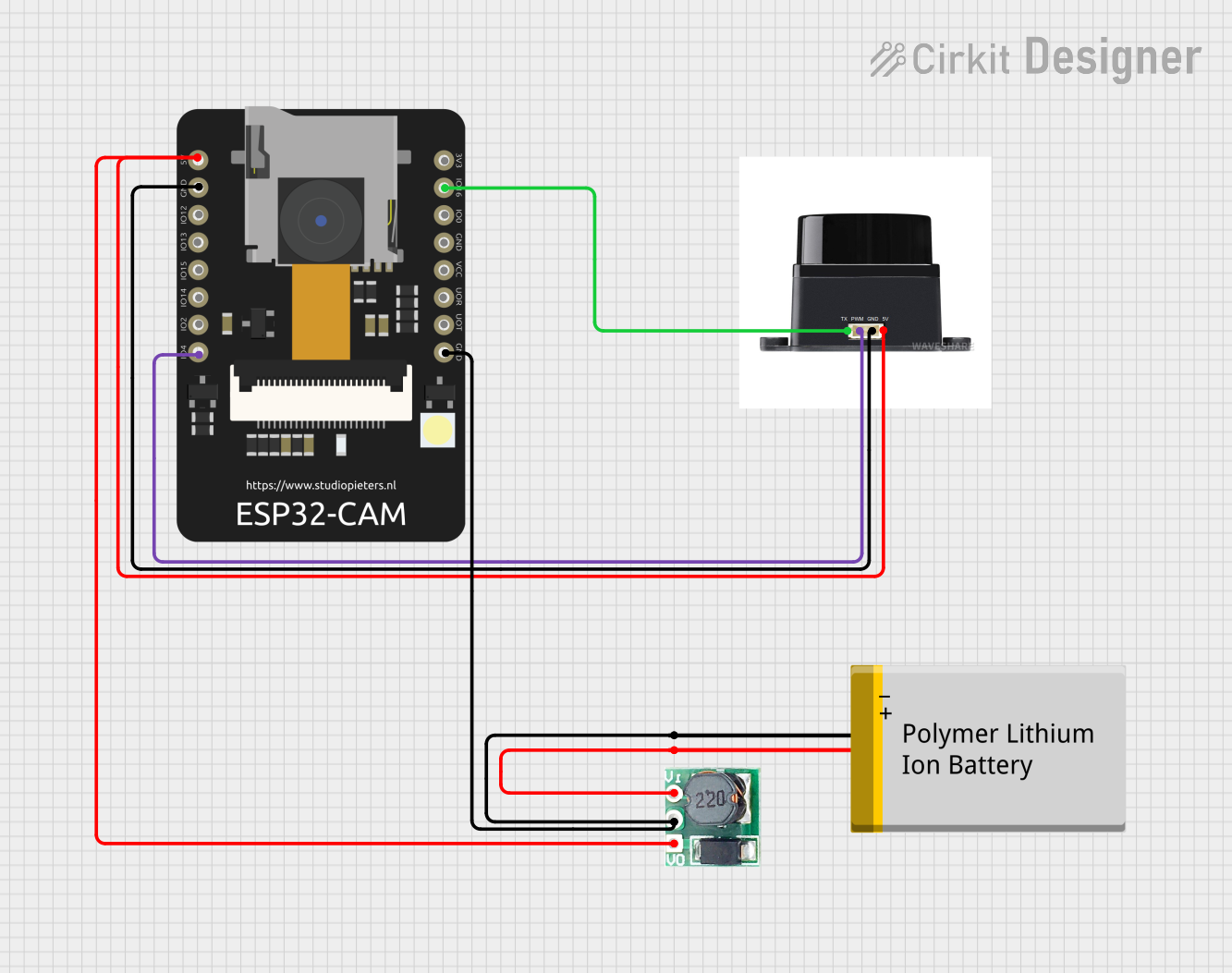
- Power the Module: Connect the 3.3V pin to a stable 3.3V power source and GND to ground.
- Connect the Camera: Attach a compatible camera module (e.g., OV2640) to the camera interface pins.
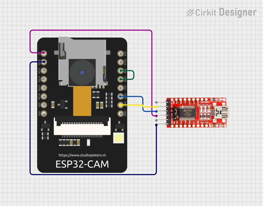
- Program the Module: Use the Arduino IDE or another compatible development environment to upload your code.
- Interface with Peripherals: Use GPIO pins to connect sensors, actuators, or other peripherals as needed.
- Establish Communication: Utilize Wi-Fi or Bluetooth for wireless communication with other devices.
Important Considerations and Best Practices
- Power Supply: Ensure a stable 3.3V power supply to avoid damage to the module.
- Boot Mode: To upload code, connect GPIO0 to GND during boot to enter programming mode.
- Camera Compatibility: Verify that the camera module is compatible with the ESP32-S3-CAM.
- Heat Management: The module may heat up during operation; ensure proper ventilation.
- Firmware Updates: Keep the firmware updated to access the latest features and bug fixes.
Example Code for Arduino UNO
Below is an example of how to use the ESP32-S3-CAM with an Arduino UNO to capture and stream video:
#include <WiFi.h>
#include <esp_camera.h>

// Replace with your network credentials
const char* ssid = "Your_SSID";
const char* password = "Your_PASSWORD";

// Camera configuration
#define PWDN_GPIO_NUM    -1
#define RESET_GPIO_NUM   -1
#define XCLK_GPIO_NUM    0
#define SIOD_GPIO_NUM    21
#define SIOC_GPIO_NUM    22
#define Y9_GPIO_NUM      35
#define Y8_GPIO_NUM      34
#define Y7_GPIO_NUM      39
#define Y6_GPIO_NUM      36
#define Y5_GPIO_NUM      19
#define Y4_GPIO_NUM      18
#define Y3_GPIO_NUM      5
#define Y2_GPIO_NUM      4
#define VSYNC_GPIO_NUM   25
#define HREF_GPIO_NUM    23
#define PCLK_GPIO_NUM    26

void setup() {
  Serial.begin(115200);

  // Connect to Wi-Fi
  WiFi.begin(ssid, password);
  while (WiFi.status() != WL_CONNECTED) {
    delay(500);
    Serial.print(".");
  }
  Serial.println("\nWiFi connected");

  // Initialize the camera
  camera_config_t config;
  config.ledc_channel = LEDC_CHANNEL_0;
  config.ledc_timer = LEDC_TIMER_0;
  config.pin_d0 = Y2_GPIO_NUM;
  config.pin_d1 = Y3_GPIO_NUM;
  config.pin_d2 = Y4_GPIO_NUM;
  config.pin_d3 = Y5_GPIO_NUM;
  config.pin_d4 = Y6_GPIO_NUM;
  config.pin_d5 = Y7_GPIO_NUM;
  config.pin_d6 = Y8_GPIO_NUM;
  config.pin_d7 = Y9_GPIO_NUM;
  config.pin_xclk = XCLK_GPIO_NUM;
  config.pin_pclk = PCLK_GPIO_NUM;
  config.pin_vsync = VSYNC_GPIO_NUM;
  config.pin_href = HREF_GPIO_NUM;
  config.pin_sscb_sda = SIOD_GPIO_NUM;
  config.pin_sscb_scl = SIOC_GPIO_NUM;
  config.pin_pwdn = PWDN_GPIO_NUM;
  config.pin_reset = RESET_GPIO_NUM;
  config.xclk_freq_hz = 20000000;
  config.pixel_format = PIXFORMAT_JPEG;

  if (esp_camera_init(&config) != ESP_OK) {
    Serial.println("Camera init failed");
    return;
  }
  Serial.println("Camera initialized");
}

void loop() {
  // Capture a frame
  camera_fb_t* fb = esp_camera_fb_get();
  if (!fb) {
    Serial.println("Camera capture failed");
    return;
  }

  // Process the frame (e.g., send it over Wi-Fi)
  Serial.printf("Captured frame size: %u bytes\n", fb->len);

  // Return the frame buffer
  esp_camera_fb_return(fb);

  delay(1000); // Capture a frame every second
}
Troubleshooting and FAQs
Common Issues and Solutions
Wi-Fi Connection Fails:
- Ensure the SSID and password are correct.
- Check if the Wi-Fi network is within range.
Camera Initialization Fails:
- Verify the camera module is properly connected.
- Ensure the camera is compatible with the ESP32-S3-CAM.
Module Overheats:
- Provide adequate ventilation or use a heat sink.
Code Upload Fails:
- Ensure GPIO0 is connected to GND during boot.
- Check the USB cable and port for proper connection.
FAQs
Q: Can I use a different camera module?
- A: Yes, as long as it is compatible with the ESP32-S3-CAM (e.g., OV2640, OV5640).
Q: What is the maximum resolution supported?
- A: The module supports resolutions up to 1600x1200 (UXGA) depending on the camera.
Q: Can I use this module for battery-powered projects?
- A: Yes, the ESP32-S3-CAM is designed for low-power applications, making it suitable for battery-powered projects.