Cirkit Designer Logo
Cirkit Designer
Your all-in-one circuit design IDE
Home / 
Component Documentation

How to Use esp32: Examples, Pinouts, and Specs

Image of esp32
Cirkit Designer LogoDesign with esp32 in Cirkit Designer

Introduction

The ESP32, manufactured by ESP, is a low-cost, low-power system on a chip (SoC) with integrated Wi-Fi and Bluetooth capabilities. It is widely used in Internet of Things (IoT) applications, embedded systems, and smart devices. The ESP32 is highly versatile, offering dual-core processing, a rich set of peripherals, and support for various communication protocols, making it a popular choice for developers and hobbyists alike.

Explore Projects Built with esp32

Use Cirkit Designer to design, explore, and prototype these projects online. Some projects support real-time simulation. Click "Open Project" to start designing instantly!
ESP32-Controlled OLED Display and Servo with DotStar LED Strip and Audio Output
Image of Arena 2: A project utilizing esp32 in a practical application
This circuit features an ESP32 microcontroller driving a variety of components. It controls an OLED display for visual output, a DotStar LED strip for lighting effects, a PAM8403 audio amplifier connected to a speaker for sound output, and a PCA9685 PWM Servo Breakout to manage a servo motor. The ESP32 also interfaces with a piezo speaker for additional sound generation, and the circuit is powered by a 18650 Li-ion battery setup with a TP4056 charging module. The ESP32's embedded code handles the display animation on the OLED.
Cirkit Designer LogoOpen Project in Cirkit Designer
ESP32-Based Sensor Monitoring System with OLED Display and E-Stop
Image of MVP_design: A project utilizing esp32 in a practical application
This circuit features an ESP32 microcontroller that interfaces with a variety of sensors and output devices. It is powered by a Lipo battery through a buck converter, ensuring a stable voltage supply. The ESP32 collects data from a DHT11 temperature and humidity sensor and a vibration sensor, controls a buzzer, and displays information on an OLED screen. An emergency stop (E Stop) is connected for safety purposes, allowing the system to be quickly deactivated.
Cirkit Designer LogoOpen Project in Cirkit Designer
ESP32-Based Environmental Monitoring System with Motion Detection
Image of pro: A project utilizing esp32 in a practical application
This circuit features an ESP32 microcontroller on a baseboard that interfaces with a PIR sensor for motion detection, a DHT22 sensor for measuring temperature and humidity, and a BH1750 sensor for detecting ambient light levels. The ESP32 is configured to communicate with the BH1750 using I2C protocol, with GPIO22 and GPIO21 serving as the SCL and SDA lines, respectively. Power is supplied to the sensors from the ESP32's voltage output pins, and sensor outputs are connected to designated GPIO pins for data acquisition.
Cirkit Designer LogoOpen Project in Cirkit Designer
ESP32-Based Smart Weather Station with Wi-Fi Connectivity
Image of flowchart 3D: A project utilizing esp32 in a practical application
This circuit features an ESP32 microcontroller interfacing with various sensors and modules, including a DHT22 temperature and humidity sensor, an ESP32 CAM for image capture, an I2C LCD screen for display, a load cell with an HX711 interface for weight measurement, and a buzzer for audio alerts. The ESP32 handles data acquisition, processing, and communication with these peripherals to create a multi-functional monitoring and alert system.
Cirkit Designer LogoOpen Project in Cirkit Designer

Explore Projects Built with esp32

Use Cirkit Designer to design, explore, and prototype these projects online. Some projects support real-time simulation. Click "Open Project" to start designing instantly!
Image of Arena 2: A project utilizing esp32 in a practical application
ESP32-Controlled OLED Display and Servo with DotStar LED Strip and Audio Output
This circuit features an ESP32 microcontroller driving a variety of components. It controls an OLED display for visual output, a DotStar LED strip for lighting effects, a PAM8403 audio amplifier connected to a speaker for sound output, and a PCA9685 PWM Servo Breakout to manage a servo motor. The ESP32 also interfaces with a piezo speaker for additional sound generation, and the circuit is powered by a 18650 Li-ion battery setup with a TP4056 charging module. The ESP32's embedded code handles the display animation on the OLED.
Cirkit Designer LogoOpen Project in Cirkit Designer
Image of MVP_design: A project utilizing esp32 in a practical application
ESP32-Based Sensor Monitoring System with OLED Display and E-Stop
This circuit features an ESP32 microcontroller that interfaces with a variety of sensors and output devices. It is powered by a Lipo battery through a buck converter, ensuring a stable voltage supply. The ESP32 collects data from a DHT11 temperature and humidity sensor and a vibration sensor, controls a buzzer, and displays information on an OLED screen. An emergency stop (E Stop) is connected for safety purposes, allowing the system to be quickly deactivated.
Cirkit Designer LogoOpen Project in Cirkit Designer
Image of pro: A project utilizing esp32 in a practical application
ESP32-Based Environmental Monitoring System with Motion Detection
This circuit features an ESP32 microcontroller on a baseboard that interfaces with a PIR sensor for motion detection, a DHT22 sensor for measuring temperature and humidity, and a BH1750 sensor for detecting ambient light levels. The ESP32 is configured to communicate with the BH1750 using I2C protocol, with GPIO22 and GPIO21 serving as the SCL and SDA lines, respectively. Power is supplied to the sensors from the ESP32's voltage output pins, and sensor outputs are connected to designated GPIO pins for data acquisition.
Cirkit Designer LogoOpen Project in Cirkit Designer
Image of flowchart 3D: A project utilizing esp32 in a practical application
ESP32-Based Smart Weather Station with Wi-Fi Connectivity
This circuit features an ESP32 microcontroller interfacing with various sensors and modules, including a DHT22 temperature and humidity sensor, an ESP32 CAM for image capture, an I2C LCD screen for display, a load cell with an HX711 interface for weight measurement, and a buzzer for audio alerts. The ESP32 handles data acquisition, processing, and communication with these peripherals to create a multi-functional monitoring and alert system.
Cirkit Designer LogoOpen Project in Cirkit Designer

Common Applications and Use Cases

  • IoT devices (e.g., smart home systems, environmental monitoring)
  • Wireless communication (Wi-Fi and Bluetooth)
  • Wearable devices
  • Robotics and automation
  • Data logging and remote sensing
  • Prototyping and educational projects

Technical Specifications

The ESP32 is a feature-rich SoC with the following key specifications:

Parameter Value
Manufacturer ESP
Part ID 32
Processor Dual-core Xtensa® 32-bit LX6 microprocessor
Clock Speed Up to 240 MHz
Flash Memory 4 MB (varies by module)
SRAM 520 KB
Wireless Connectivity Wi-Fi 802.11 b/g/n, Bluetooth v4.2 + BLE
Operating Voltage 3.0V to 3.6V
GPIO Pins 34 (multiplexed with other functions)
ADC Channels 18 (12-bit resolution)
DAC Channels 2
Communication Interfaces UART, SPI, I2C, I2S, CAN, PWM
Power Consumption Ultra-low power (supports deep sleep mode with <10 µA current draw)
Operating Temperature -40°C to +125°C

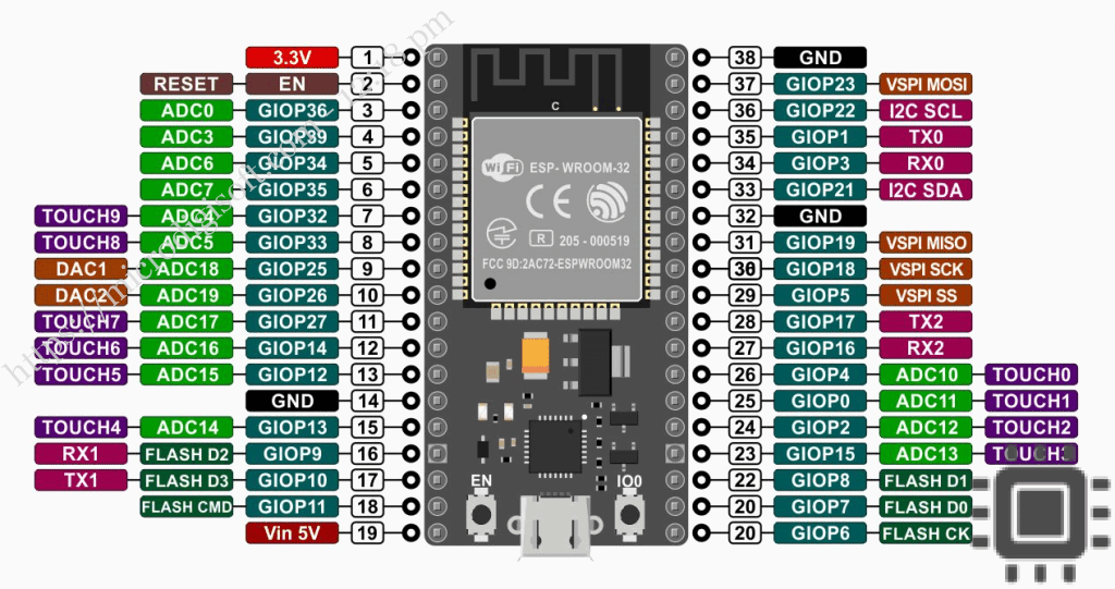
Pin Configuration and Descriptions

The ESP32 has a variety of pins, each with specific functions. Below is a table summarizing the key pin configurations:

Pin Name Function Description
GPIO0 Input/Output, Boot Mode Select Used for boot mode selection during startup.
GPIO2 Input/Output, ADC, PWM General-purpose I/O, supports ADC and PWM.
GPIO12 Input/Output, ADC, Touch Sensor General-purpose I/O, supports ADC and capacitive touch sensing.
GPIO13 Input/Output, ADC, Touch Sensor General-purpose I/O, supports ADC and capacitive touch sensing.
GPIO15 Input/Output, ADC, PWM General-purpose I/O, supports ADC and PWM.
EN Enable Active-high pin to enable or reset the chip.
3V3 Power Supply Provides 3.3V power to the ESP32.
GND Ground Ground connection.

For a complete pinout, refer to the ESP32 datasheet provided by the manufacturer.

Usage Instructions

How to Use the ESP32 in a Circuit

  1. Power Supply: Connect the 3V3 pin to a 3.3V power source and GND to ground. Ensure the power supply can provide sufficient current (at least 500 mA).
  2. Programming: Use a USB-to-serial adapter or a development board (e.g., ESP32 DevKit) to program the ESP32. The chip supports programming via the Arduino IDE, PlatformIO, or ESP-IDF.
  3. Boot Mode: To enter bootloader mode for programming, connect GPIO0 to GND and reset the chip.
  4. Peripherals: Connect sensors, actuators, or other peripherals to the GPIO pins. Use appropriate pull-up or pull-down resistors as needed.

Important Considerations and Best Practices

  • Voltage Levels: The ESP32 operates at 3.3V logic levels. Avoid connecting 5V signals directly to its GPIO pins.
  • Power Consumption: Use deep sleep mode to minimize power consumption in battery-powered applications.
  • Antenna Placement: Ensure the onboard antenna has sufficient clearance from metal objects to avoid signal interference.
  • Heat Management: The ESP32 can get warm during operation. Ensure proper ventilation if used in enclosed spaces.

Example Code for Arduino UNO Integration

Below is an example of how to use the ESP32 with the Arduino IDE to connect to a Wi-Fi network:

#include <WiFi.h> // Include the Wi-Fi library for ESP32

// Replace with your network credentials
const char* ssid = "Your_SSID";       // Your Wi-Fi network name
const char* password = "Your_PASSWORD"; // Your Wi-Fi network password

void setup() {
  Serial.begin(115200); // Initialize serial communication at 115200 baud
  delay(1000);          // Wait for a second to stabilize the serial monitor

  Serial.println("Connecting to Wi-Fi...");
  WiFi.begin(ssid, password); // Start connecting to the Wi-Fi network

  while (WiFi.status() != WL_CONNECTED) {
    delay(500); // Wait for 500ms before checking the connection status again
    Serial.print(".");
  }

  Serial.println("\nWi-Fi connected!");
  Serial.print("IP Address: ");
  Serial.println(WiFi.localIP()); // Print the assigned IP address
}

void loop() {
  // Add your main code here
}

Troubleshooting and FAQs

Common Issues and Solutions

  1. ESP32 Not Connecting to Wi-Fi

    • Solution: Double-check the SSID and password. Ensure the Wi-Fi network is operational and within range.
    • Tip: Use WiFi.status() to debug connection issues.
  2. GPIO Pins Not Responding

    • Solution: Verify the pin configuration in your code. Ensure no conflicting peripherals are using the same pins.
    • Tip: Use a multimeter to check for proper voltage levels on the pins.
  3. ESP32 Not Entering Bootloader Mode

    • Solution: Ensure GPIO0 is connected to GND during reset. Check the USB-to-serial adapter connection.
    • Tip: Use a development board with an onboard USB interface for easier programming.
  4. Overheating

    • Solution: Reduce the clock speed or optimize the code to minimize processing load.
    • Tip: Ensure proper ventilation and avoid placing the ESP32 in enclosed spaces.

FAQs

  • Q: Can the ESP32 operate on 5V?

    • A: No, the ESP32 operates at 3.3V. Use a voltage regulator or level shifter for 5V systems.
  • Q: How do I update the ESP32 firmware?

    • A: Use the ESP-IDF or Arduino IDE to upload new firmware via the USB interface.
  • Q: Can the ESP32 handle multiple tasks simultaneously?

    • A: Yes, the ESP32 supports FreeRTOS, allowing multitasking with multiple threads.

This documentation provides a comprehensive guide to using the ESP32. For further details, refer to the official ESP32 datasheet and programming guides.