How to Use DS3: Examples, Pinouts, and Specs
Introduction
The DS3 is a Zener diode manufactured by APSYSTEM, designed for voltage regulation and circuit protection. It operates by allowing current to flow in the reverse direction once a specific reverse breakdown voltage is reached. This makes it ideal for maintaining a stable voltage across sensitive components and protecting circuits from overvoltage conditions.
Explore Projects Built with DS3
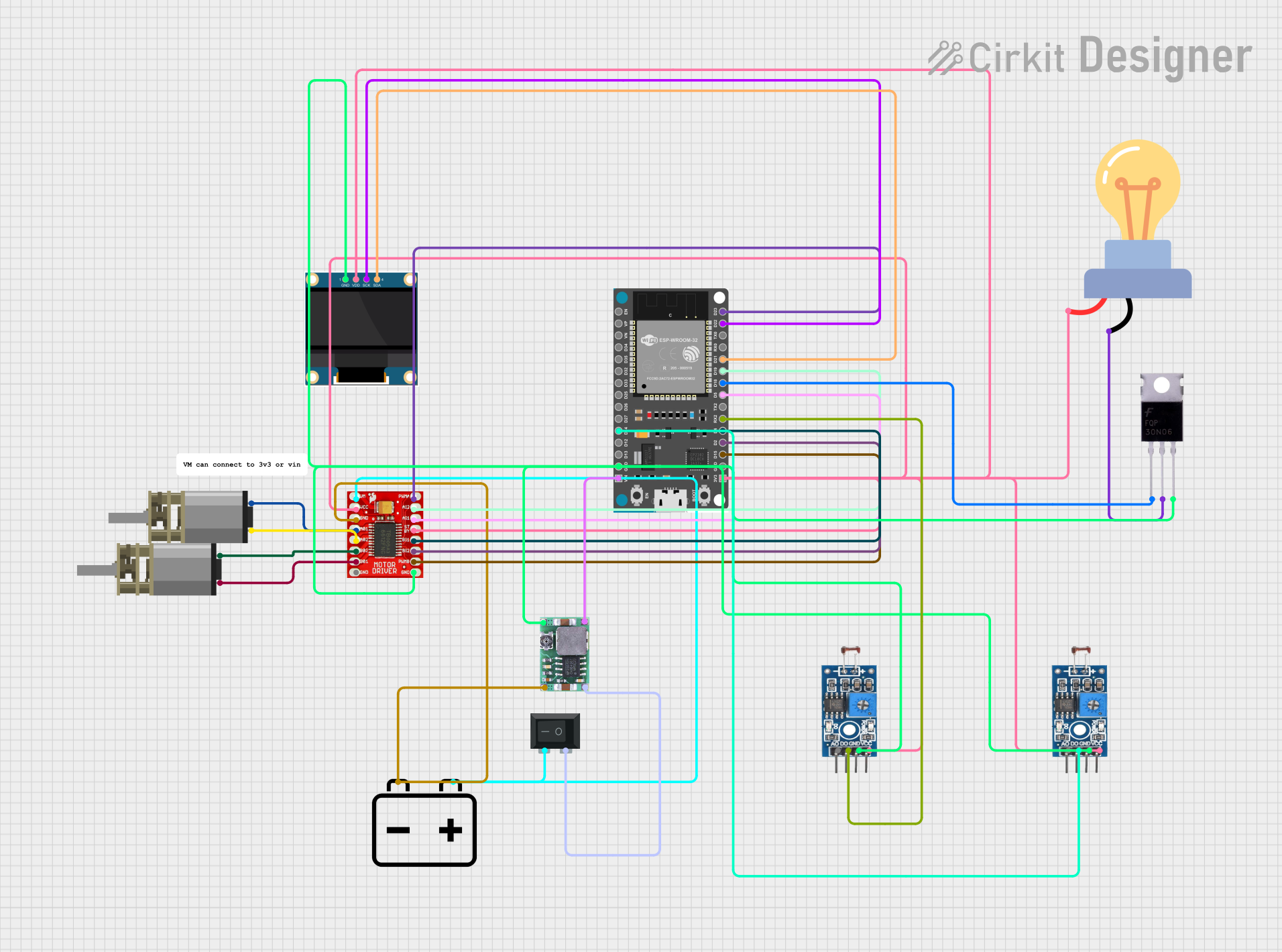

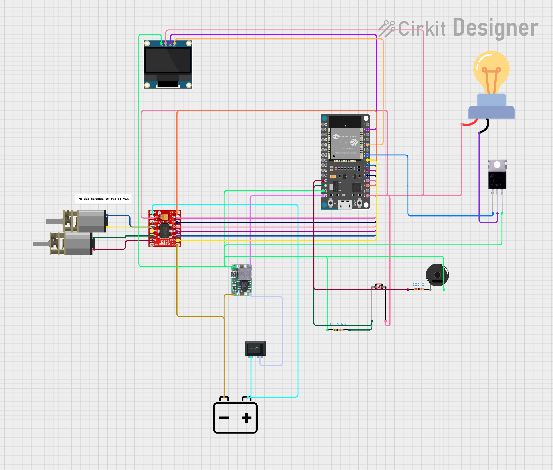

Explore Projects Built with DS3
Common Applications and Use Cases
- Voltage regulation in power supplies
- Overvoltage protection in electronic circuits
- Reference voltage generation
- Clamping circuits to limit voltage spikes
- Used in combination with resistors for simple voltage regulation setups
Technical Specifications
The DS3 Zener diode is engineered for reliable performance in a variety of electronic applications. Below are its key technical specifications:
| Parameter | Value |
|---|---|
| Zener Voltage (Vz) | 3.3V |
| Tolerance | ±5% |
| Maximum Power Dissipation (Pmax) | 500 mW |
| Maximum Reverse Current (Ir) | 5 µA @ Vz |
| Operating Temperature | -55°C to +150°C |
| Package Type | DO-35 |
Pin Configuration and Descriptions
The DS3 Zener diode has two pins, as described below:
| Pin | Name | Description |
|---|---|---|
| 1 | Cathode (-) | Connected to the negative terminal of the circuit |
| 2 | Anode (+) | Connected to the positive terminal of the circuit |
Usage Instructions
How to Use the DS3 in a Circuit
- Determine the Zener Voltage (Vz): Ensure the DS3's Zener voltage (3.3V) matches the desired regulated voltage in your circuit.
- Connect the Diode:
- Connect the cathode (marked with a band) to the positive voltage source.
- Connect the anode to the ground or the lower voltage side of the circuit.
- Add a Series Resistor: To limit the current through the diode, place a resistor in series with the DS3. Calculate the resistor value using Ohm's Law:
[
R = \frac{V_{in} - V_z}{I_z}
]
Where:
- ( V_{in} ) is the input voltage.
- ( V_z ) is the Zener voltage (3.3V for the DS3).
- ( I_z ) is the desired current through the diode.
Important Considerations and Best Practices
- Power Dissipation: Ensure the power dissipation across the DS3 does not exceed its maximum rating of 500 mW. Use the formula ( P = V_z \times I_z ) to calculate power dissipation.
- Reverse Current: Avoid exceeding the maximum reverse current (5 µA) to prevent damage to the diode.
- Temperature Range: Operate the DS3 within its specified temperature range (-55°C to +150°C) for optimal performance.
- Polarity: Double-check the polarity of the diode before connecting it to the circuit to avoid malfunction.
Example: Using the DS3 with an Arduino UNO
The DS3 can be used to regulate voltage for an Arduino UNO or protect it from overvoltage. Below is an example circuit and code to monitor the regulated voltage:
Circuit Setup
- Connect the DS3 Zener diode in reverse bias across the input voltage.
- Place a 330Ω resistor in series with the diode to limit current.
- Connect the regulated voltage to an analog input pin on the Arduino.
Arduino Code
// Arduino code to monitor the voltage regulated by the DS3 Zener diode
const int voltagePin = A0; // Analog pin connected to the regulated voltage
float referenceVoltage = 5.0; // Arduino reference voltage (5V)
int adcResolution = 1024; // ADC resolution (10-bit)

void setup() {
  Serial.begin(9600); // Initialize serial communication
}

void loop() {
  int sensorValue = analogRead(voltagePin); // Read the analog input
  // Calculate the voltage based on the ADC value
  float voltage = (sensorValue * referenceVoltage) / adcResolution;

  // Print the voltage to the Serial Monitor
  Serial.print("Regulated Voltage: ");
  Serial.print(voltage);
  Serial.println(" V");

  delay(1000); // Wait for 1 second before the next reading
}
Troubleshooting and FAQs
Common Issues and Solutions
No Voltage Regulation:
- Cause: Incorrect polarity of the diode.
- Solution: Verify that the cathode is connected to the positive voltage source and the anode to the ground.
Excessive Heat:
- Cause: Current through the diode exceeds its maximum rating.
- Solution: Use a higher-value series resistor to limit the current.
Voltage Drop Below Zener Voltage:
- Cause: Insufficient input voltage.
- Solution: Ensure the input voltage is at least 1V higher than the Zener voltage (3.3V).
Arduino Reads Incorrect Voltage:
- Cause: Incorrect reference voltage or ADC resolution in the code.
- Solution: Verify the Arduino's reference voltage and update the code accordingly.
FAQs
Q: Can the DS3 be used for AC voltage regulation?
A: No, the DS3 is designed for DC voltage regulation. For AC applications, additional components like rectifiers are required.
Q: What happens if the input voltage is too high?
A: If the input voltage significantly exceeds the Zener voltage, the diode may overheat and fail. Always use a series resistor to limit current.
Q: Can I use the DS3 without a series resistor?
A: No, a series resistor is essential to prevent excessive current through the diode, which could damage it.
Q: How do I calculate the power dissipation of the DS3?
A: Use the formula ( P = V_z \times I_z ), where ( V_z ) is the Zener voltage and ( I_z ) is the current through the diode. Ensure the result does not exceed 500 mW.