How to Use RP2040-Lora: Examples, Pinouts, and Specs
Introduction
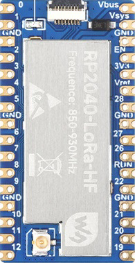
The RP2040-Lora is a microcontroller board developed by Waveshare (Part ID: RP2040-SX1262). It integrates the powerful Raspberry Pi RP2040 microcontroller with the SX1262 LoRa module, enabling long-range, low-power wireless communication. This combination makes it ideal for Internet of Things (IoT) applications, remote sensing, and other projects requiring reliable, long-distance data transmission.
Explore Projects Built with RP2040-Lora


Explore Projects Built with RP2040-Lora
Common Applications and Use Cases
- IoT networks for smart cities, agriculture, and industrial automation
- Environmental monitoring and remote sensing
- Low-power wireless communication in rural or remote areas
- LoRaWAN-based applications
- Wireless data logging and telemetry
Technical Specifications
Key Technical Details
| Parameter | Specification |
|---|---|
| Microcontroller | Raspberry Pi RP2040 |
| LoRa Module | SX1262 |
| Operating Voltage | 3.3V |
| Input Voltage Range | 5V (via USB-C) |
| Flash Memory | 2MB QSPI Flash |
| SRAM | 264KB |
| LoRa Frequency Bands | 868MHz (EU) / 915MHz (US) |
| Communication Interfaces | SPI, I2C, UART, GPIO |
| Power Consumption | Ultra-low power (depends on LoRa transmission) |
| Dimensions | 51mm x 21mm |
| Operating Temperature | -40°C to +85°C |
Pin Configuration and Descriptions
The RP2040-Lora features a 20-pin header for GPIO and communication interfaces. Below is the pinout:
| Pin Number | Pin Name | Description |
|---|---|---|
| 1 | 3V3 | 3.3V Power Output |
| 2 | GND | Ground |
| 3 | GP0 | General Purpose I/O (GPIO) |
| 4 | GP1 | General Purpose I/O (GPIO) |
| 5 | GP2 | General Purpose I/O (GPIO) |
| 6 | GP3 | General Purpose I/O (GPIO) |
| 7 | GP4 | General Purpose I/O (GPIO) |
| 8 | GP5 | General Purpose I/O (GPIO) |
| 9 | GP6 | General Purpose I/O (GPIO) |
| 10 | GP7 | General Purpose I/O (GPIO) |
| 11 | GP8 | General Purpose I/O (GPIO) |
| 12 | GP9 | General Purpose I/O (GPIO) |
| 13 | GP10 | General Purpose I/O (GPIO) |
| 14 | GP11 | General Purpose I/O (GPIO) |
| 15 | GP12 | General Purpose I/O (GPIO) |
| 16 | GP13 | General Purpose I/O (GPIO) |
| 17 | GP14 | General Purpose I/O (GPIO) |
| 18 | GP15 | General Purpose I/O (GPIO) |
| 19 | GP16 | General Purpose I/O (GPIO) |
| 20 | GP17 | General Purpose I/O (GPIO) |
Usage Instructions
How to Use the Component in a Circuit
Powering the Board:
- Connect the RP2040-Lora to a 5V USB-C power source. The onboard voltage regulator will provide the required 3.3V to the microcontroller and LoRa module.
Connecting Peripherals:
- Use the GPIO pins to connect sensors, actuators, or other peripherals. Ensure that all connected devices operate at 3.3V logic levels to avoid damage.
Programming the Board:
- The RP2040-Lora can be programmed using the C/C++ SDK or MicroPython. Connect the board to your computer via USB-C and upload your code using a compatible IDE (e.g., Thonny for MicroPython or Visual Studio Code for C/C++).
LoRa Communication:
- Use the SPI interface to communicate with the SX1262 LoRa module. Libraries such as the Arduino LoRa library or custom drivers can simplify the process.
Important Considerations and Best Practices
- Voltage Levels: Ensure all connected devices operate at 3.3V logic levels. Use level shifters if interfacing with 5V devices.
- Antenna Connection: Attach a suitable LoRa antenna to the SMA connector for optimal performance.
- Frequency Band: Configure the LoRa module to operate within the allowed frequency band for your region (e.g., 868MHz for Europe, 915MHz for the US).
- Power Consumption: Use sleep modes and optimize transmission intervals to minimize power consumption in battery-powered applications.
Example Code for Arduino UNO
Below is an example of how to use the RP2040-Lora with an Arduino UNO to send a LoRa message:
#include <SPI.h>
#include <LoRa.h>

// Define LoRa module pins
#define LORA_SCK 5    // SPI Clock
#define LORA_MISO 19  // SPI MISO
#define LORA_MOSI 27  // SPI MOSI
#define LORA_CS 18    // Chip Select
#define LORA_RST 14   // Reset
#define LORA_IRQ 26   // IRQ Pin

void setup() {
  // Initialize serial communication
  Serial.begin(9600);
  while (!Serial);

  // Initialize LoRa module
  Serial.println("Initializing LoRa...");
  if (!LoRa.begin(915E6)) { // Set frequency to 915 MHz
    Serial.println("LoRa initialization failed!");
    while (1);
  }
  Serial.println("LoRa initialized successfully.");
}

void loop() {
  // Send a test message
  Serial.println("Sending message...");
  LoRa.beginPacket();
  LoRa.print("Hello, LoRa!");
  LoRa.endPacket();

  // Wait for 5 seconds before sending the next message
  delay(5000);
}
Notes:
- Replace the frequency
915E6with868E6if operating in Europe. - Ensure the LoRa module pins are correctly connected to the Arduino UNO.
Troubleshooting and FAQs
Common Issues and Solutions
LoRa Module Not Initializing:
- Ensure the SPI pins are correctly connected and configured in the code.
- Verify that the LoRa module is powered and the antenna is connected.
No Data Transmission:
- Check that both sender and receiver are configured to the same frequency and spreading factor.
- Ensure the devices are within range and there are no significant obstructions.
High Power Consumption:
- Use sleep modes for the RP2040 and SX1262 when not actively transmitting.
- Reduce the transmission frequency or data rate.
Programming Issues:
- Ensure the correct drivers for the RP2040 are installed on your computer.
- Use a compatible USB cable for data transfer (not just a charging cable).
FAQs
Q: Can I use the RP2040-Lora with LoRaWAN?
A: Yes, the SX1262 module supports LoRaWAN. You will need to implement a LoRaWAN stack or use a library that supports it.
Q: What is the maximum range of the RP2040-Lora?
A: The range depends on environmental factors, but it can reach up to 10 km in open areas with a clear line of sight.
Q: Can I power the board with a battery?
A: Yes, you can use a 3.7V LiPo battery with a suitable voltage regulator to provide 3.3V to the board.
Q: Is the RP2040-Lora compatible with MicroPython?
A: Yes, the RP2040 microcontroller supports MicroPython, and you can use it to program the board.