How to Use Battery Charge & Discharge UPS Module: Examples, Pinouts, and Specs
Introduction
The Battery Charge & Discharge UPS Module by Rsdz Store is a versatile device designed to manage the charging and discharging of batteries in uninterruptible power supply (UPS) systems. It ensures a stable power output during power outages, protecting connected devices from sudden shutdowns or damage. This module is ideal for applications requiring reliable backup power, such as IoT devices, Raspberry Pi systems, Arduino projects, and other low-power electronics.
Explore Projects Built with Battery Charge & Discharge UPS Module

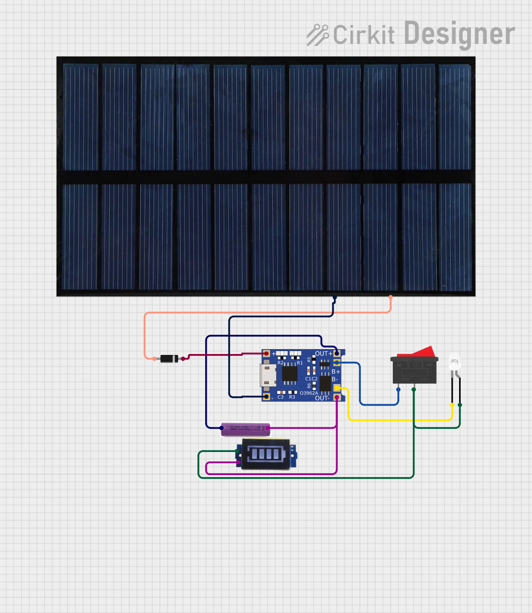
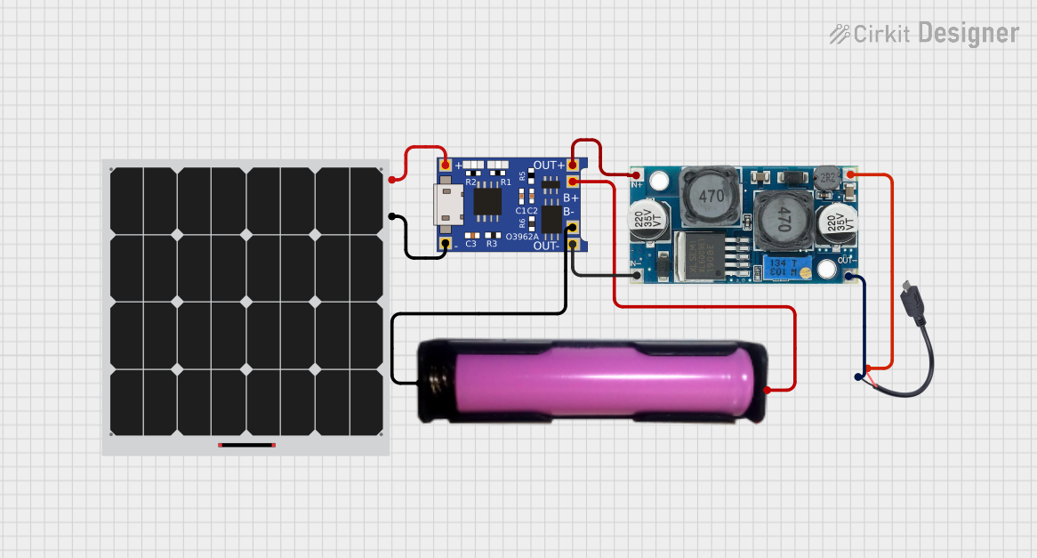
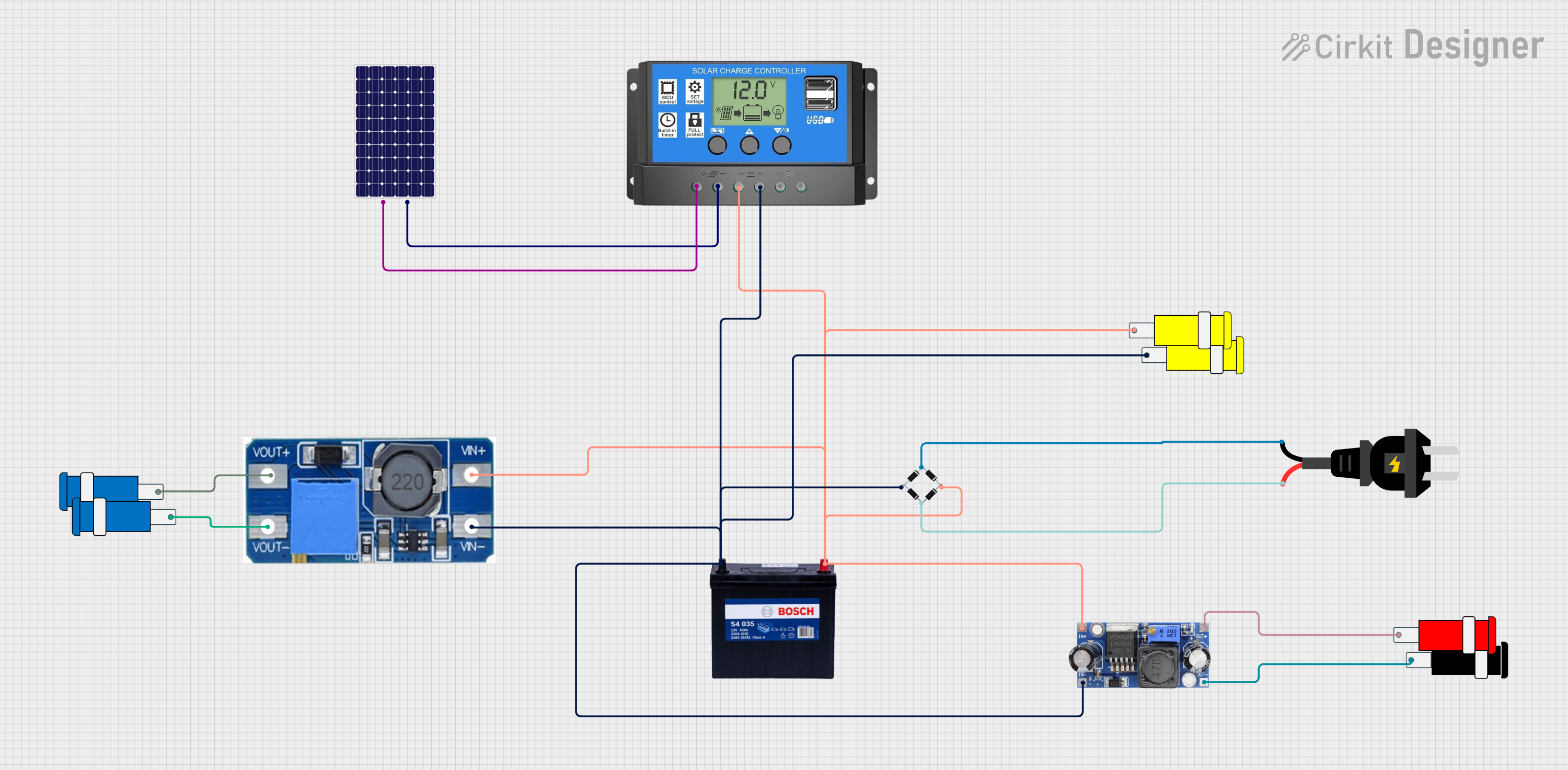
Explore Projects Built with Battery Charge & Discharge UPS Module
Common Applications and Use Cases
- Backup power for microcontroller-based systems (e.g., Arduino, Raspberry Pi)
- IoT devices requiring uninterrupted operation
- Portable electronics with rechargeable batteries
- Emergency lighting systems
- Small-scale renewable energy systems (e.g., solar-powered setups)
Technical Specifications
Below are the key technical details of the Battery Charge & Discharge UPS Module:
| Parameter | Value |
|---|---|
| Input Voltage Range | 5V to 9V DC |
| Output Voltage | 5V DC (regulated) |
| Maximum Output Current | 2A |
| Battery Type Supported | Lithium-ion (3.7V nominal, 4.2V fully charged) |
| Charging Current | 1A (default, adjustable via resistor) |
| Protection Features | Overcharge, over-discharge, short-circuit |
| Dimensions | 50mm x 25mm x 10mm |
| Operating Temperature | -20°C to 60°C |
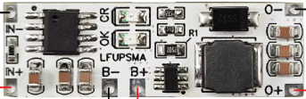
Pin Configuration and Descriptions
The module has several pins and connectors for input, output, and battery connections. Below is the pin configuration:
| Pin/Connector | Label | Description |
|---|---|---|
| Input Connector | VIN | Connect to a DC power source (5V to 9V) |
| Output Connector | VOUT | Provides regulated 5V output for connected devices |
| Battery Connector | BAT | Connect to a 3.7V lithium-ion battery |
| Status LED | CHG | Indicates charging status (ON = charging) |
| Status LED | PWR | Indicates power output status (ON = power active) |
Usage Instructions
How to Use the Component in a Circuit
- Connect the Battery: Attach a 3.7V lithium-ion battery to the BAT connector. Ensure correct polarity to avoid damage.
- Connect the Input Power Source: Supply 5V to 9V DC to the VIN connector. This will charge the battery and power the output simultaneously.
- Connect the Load: Attach your device or circuit to the VOUT connector. The module will provide a stable 5V output.
- Monitor LEDs: Use the CHG and PWR LEDs to monitor the charging and power output status.
Important Considerations and Best Practices
- Battery Selection: Use only high-quality lithium-ion batteries with built-in protection circuits to ensure safety.
- Heat Dissipation: Avoid enclosing the module in a tight space without ventilation, as it may generate heat during operation.
- Input Voltage: Ensure the input voltage does not exceed 9V to prevent damage to the module.
- Load Current: Do not exceed the maximum output current of 2A to avoid overloading the module.
- Arduino/Raspberry Pi Usage: When using this module with an Arduino or Raspberry Pi, connect the VOUT pin to the 5V input pin of the board.
Example Code for Arduino UNO
Below is an example of how to monitor the battery voltage using an Arduino UNO:
// Example code to monitor battery voltage using Arduino UNO
// Connect the BAT pin of the module to an analog input pin (e.g., A0)

const int batteryPin = A0;  // Analog pin connected to BAT pin
float batteryVoltage = 0.0;

void setup() {
  Serial.begin(9600);  // Initialize serial communication
}

void loop() {
  int sensorValue = analogRead(batteryPin);  // Read analog value
  // Convert the analog value to voltage (assuming 10-bit ADC and 5V reference)
  batteryVoltage = sensorValue * (5.0 / 1023.0);

  // Print the battery voltage to the Serial Monitor
  Serial.print("Battery Voltage: ");
  Serial.print(batteryVoltage);
  Serial.println(" V");

  delay(1000);  // Wait for 1 second before the next reading
}
Troubleshooting and FAQs
Common Issues and Solutions
Module Not Powering On
- Cause: Incorrect input voltage or loose connections.
- Solution: Verify that the input voltage is within the 5V to 9V range and check all connections.
Battery Not Charging
- Cause: Faulty battery or incorrect polarity.
- Solution: Ensure the battery is functional and connected with the correct polarity.
Output Voltage is Unstable
- Cause: Overloaded output or insufficient input power.
- Solution: Reduce the load current or ensure the input power source can supply sufficient current.
Module Overheating
- Cause: Prolonged operation at maximum current or poor ventilation.
- Solution: Reduce the load or improve ventilation around the module.
FAQs
Can I use this module with a 12V power source? No, the maximum input voltage is 9V. Using a 12V source may damage the module.
What happens if the battery is fully charged? The module automatically stops charging the battery to prevent overcharging.
Can I use this module with a NiMH or lead-acid battery? No, this module is specifically designed for 3.7V lithium-ion batteries.
Is it safe to leave the module connected to the battery and load indefinitely? Yes, the module includes protection features to ensure safe operation during continuous use.