How to Use 4 DIGIT TIMER MODULE: Examples, Pinouts, and Specs
Introduction
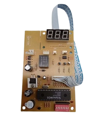
The ALLAN 4 DIGIT TIMER is a versatile digital timer module designed to display time in a four-digit format. It is commonly used in electronic projects for countdowns, time tracking, and event scheduling. The module features a bright LED display, making it suitable for applications requiring clear and precise time visualization. Its compact design and ease of integration make it a popular choice for hobbyists and professionals alike.
Explore Projects Built with 4 DIGIT TIMER MODULE
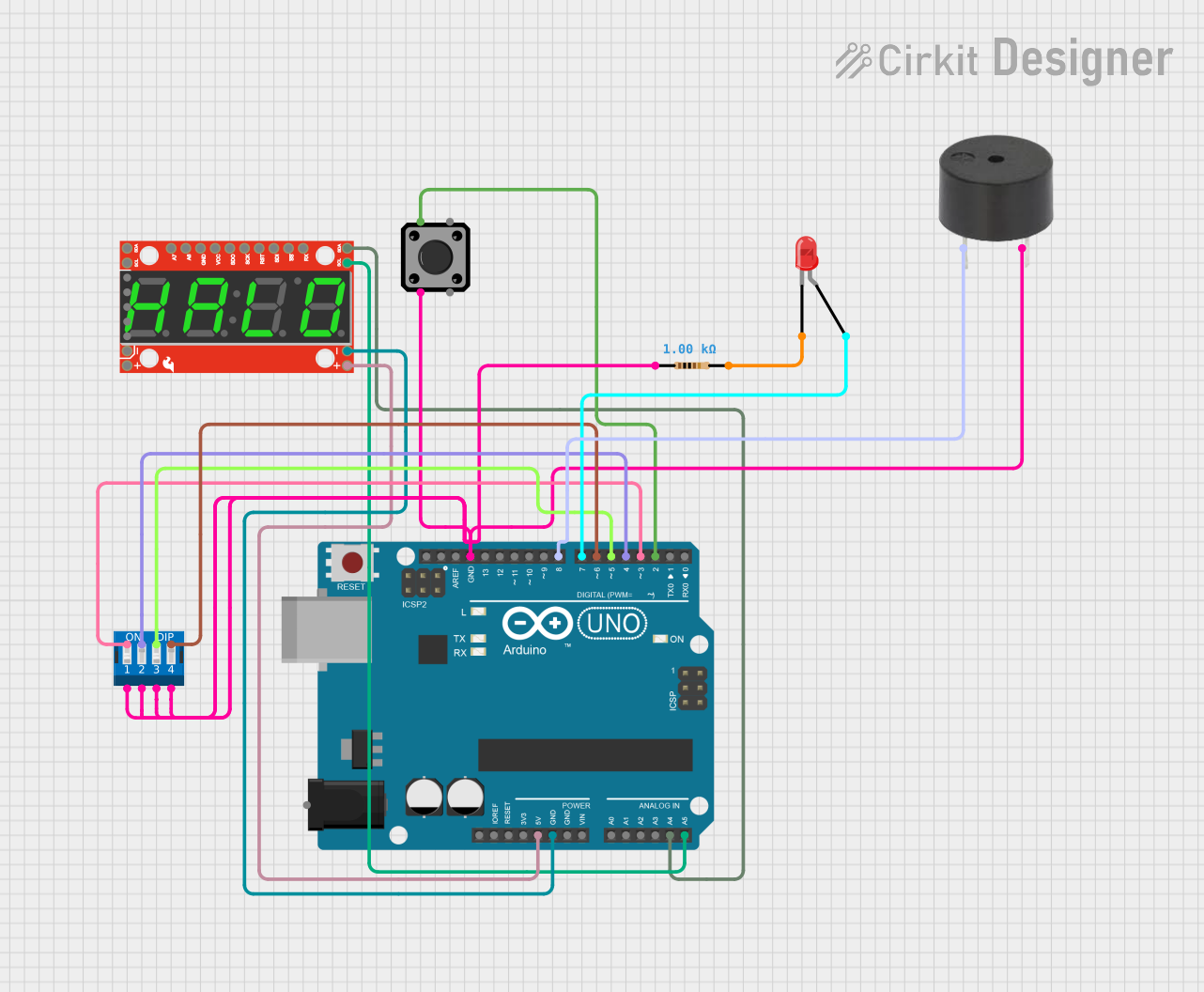
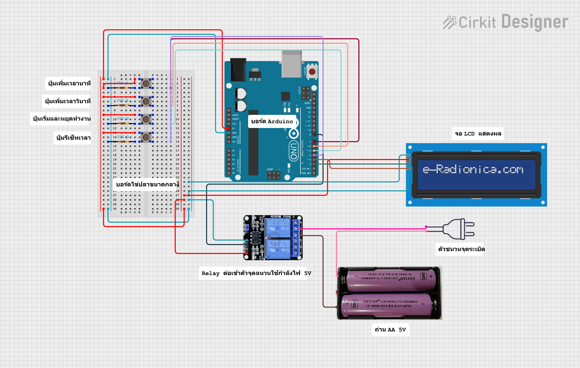

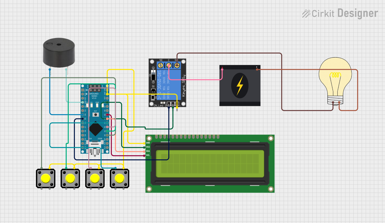
Explore Projects Built with 4 DIGIT TIMER MODULE
Common Applications
- Countdown timers for DIY projects
- Time tracking in industrial or home automation systems
- Stopwatch functionality in sports or experiments
- Event scheduling in embedded systems
- Educational projects for learning about timers and displays
Technical Specifications
Key Technical Details
| Parameter | Specification |
|---|---|
| Manufacturer | ALLAN |
| Part ID | ALLAN 4 DIGIT TIMER |
| Operating Voltage | 5V DC |
| Operating Current | 20-50 mA (depending on brightness) |
| Display Type | 4-digit 7-segment LED display |
| Display Color | Red |
| Timing Range | 0 to 9999 seconds (configurable) |
| Dimensions | 50mm x 25mm x 15mm |
| Interface | 4-pin interface (VCC, GND, CLK, DIO) |
| Communication Protocol | Serial (based on TM1637 driver IC) |
Pin Configuration
The module has a 4-pin interface for easy connection to microcontrollers. Below is the pin configuration:
| Pin Name | Description |
|---|---|
| VCC | Power supply input (5V DC) |
| GND | Ground |
| CLK | Clock signal for serial communication |
| DIO | Data input/output for serial communication |
Usage Instructions
How to Use the Component in a Circuit
- Power the Module: Connect the
VCCpin to a 5V power source and theGNDpin to ground. - Connect to a Microcontroller: Use the
CLKandDIOpins to interface with a microcontroller, such as an Arduino UNO. - Install Required Libraries: If using an Arduino, install the
TM1637Displaylibrary to simplify communication with the module. - Write and Upload Code: Use the provided example code or write your own to control the timer and display values.
Important Considerations
- Ensure the power supply is stable and within the specified voltage range (5V DC).
- Avoid connecting the module directly to higher voltage sources to prevent damage.
- Use pull-up resistors on the
CLKandDIOlines if communication issues occur. - Keep the module away from high-temperature environments to maintain display longevity.
Example Code for Arduino UNO
Below is an example code snippet to display a countdown timer using the ALLAN 4 DIGIT TIMER module:
#include <TM1637Display.h>

// Define the CLK and DIO pins connected to the module
#define CLK 2  // Clock pin
#define DIO 3  // Data pin

// Initialize the TM1637Display object
TM1637Display display(CLK, DIO);

void setup() {
  display.setBrightness(7); // Set display brightness (0-7)
}

void loop() {
  // Countdown timer from 30 seconds
  for (int i = 30; i >= 0; i--) {
    display.showNumberDec(i, true); // Display the number on the module
    delay(1000); // Wait for 1 second
  }

  // Display "0000" when countdown ends
  display.showNumberDec(0, true);
  delay(5000); // Wait for 5 seconds before restarting
}
Notes:
- The
TM1637Displaylibrary can be installed via the Arduino Library Manager. - Adjust the
CLKandDIOpin definitions to match your circuit connections.
Troubleshooting and FAQs
Common Issues and Solutions
| Issue | Possible Cause | Solution |
|---|---|---|
| Display not turning on | Incorrect power connection | Verify VCC and GND connections. |
| Flickering or dim display | Insufficient power supply | Use a stable 5V DC power source. |
| No response from the module | Incorrect CLK or DIO connections |
Check and reconnect the CLK and DIO pins. |
| Incorrect or garbled display output | Communication error | Ensure proper library installation and correct pin definitions in the code. |
| Timer not counting down | Code logic error | Review and debug the uploaded code. |
FAQs
Can I use this module with a 3.3V microcontroller?
- The module is designed for 5V operation. Use a level shifter if interfacing with a 3.3V microcontroller.
How do I adjust the brightness of the display?
- Use the
setBrightness()function in theTM1637Displaylibrary. Brightness levels range from 0 (dim) to 7 (bright).
- Use the
What is the maximum timing range of the module?
- The module can display up to 9999 seconds. For longer durations, additional logic is required in the code.
Can I display letters or custom characters?
- The module primarily supports numeric values. However, some letters (e.g., "A", "b", "C") can be displayed using custom segment configurations.
By following this documentation, users can effectively integrate and utilize the ALLAN 4 DIGIT TIMER module in their projects.